Feeler - ez1081pre - 500 series Class A/B

GroupDIY Audio Forum

Help Support GroupDIY Audio Forum:

This site may earn a commission from merchant affiliate links, including eBay, Amazon, and others.

Slenderchap

Well-known member
Joined
Mar 10, 2005
Messages
617
Location
Manchester, UK
Too early for Christmas this time....  but couldn't wait.
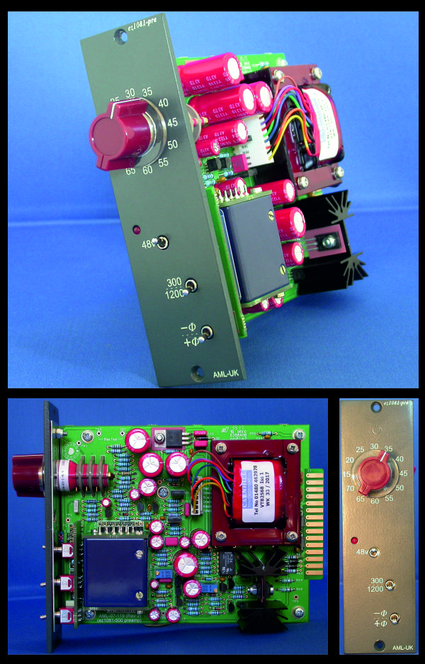
                                                   
ez1081pre composite - 600.jpg


It is the ez1081pre  ..... 500 series version of a classic Class A/B mic-pre..... there's a clue is in the name....

It is a significantly simpler project than the other kits we do so it can be completed by less experienced project builders.

Build instructions are here:
http://www.audiomaintenance.com/downloads/ez1081pre_colourbook.pdf

(Apparently the sound is somewhere between an API312 and a Neve 1073)

........... "any interest" ?

Colin
www.audiomaintenance.com
 
ez1081pre's are in stock.

ez2254 is just out of stock for a few weeks. (as is ezP-1a & ezMEQ5).

1081 EQ is far to big for 500 series.

Colin.
www.audiomaintenance.com
 
Hey all,

Anyone built these yet? I built 4 but am having trouble calibrating one of them - can't get the trimmer to get to 20dBU - it hits the end stop around 13-14dBU on the output so I'm losing some gain somewhere.......

Anyone got any ideas as to where to start looking?
 
Indeed it was! Thanks Colin for spotting that so quickly.

Awesome kits - just fired them up in the patchbay for a quick test and they sound great!
 
Hey Collin,

Nice work, as always  - especially interested in the +24VDC +B referenced to the -16V power rail for the neve amp stages.

Do you know offhand what kind of noise/ripple you are getting?

Thanks for sharing.
Timothy
 
Old topic but I thought I'd hit it up as I'm in a strange situation. A friend of mine built one of these and asked me to help him because he couldn't figure out what's wrong....

Right away it was apparent to me that something was very wrong....
Due to all the resistors having short leads, he soldered from the top everything except those things he couldn't like capacitors. Very strange.

The whole bottom of the PCB looked like floating leads. So I fixed that.

Next, the two regulators weren't attached to the heatsink. He just had them floating bent away from each other with gobs of solder. When I removed them there was a burnt resistor that became apparent to me R65, which is a surge control. Replaced that.

I guess he tried replacing a capacitor that bulged. C20. He tried replacing it but didn't solder suck anything so he basically stuck the capacitor as far down as he could while soldering the top. So the leads are like an inch long. Replaced that.

Next I checked the functionality of the diodes. There is so many non-working diodes on this thing that it doesn't even make sense. I feel like It's maybe because he heated them from the top and they got too hot or something...because they're pretty much all messed up. I'm going to go ahead an assume that all the BC550c and BC560C are messed up from the regulators.

Now here is the thing. I think that what caused this problem was probably that he lifted  the copper on two solder holes. So one side probably didn't have continuity with where it was going. He removed the heatsink and poorly soldered them back in, I'm assuming because he had them reversed the first time, which may be what caused the initial problem. Then when we "fixed it" it didn't work because a regulator was fried as well as a bunch of diodes and probably all the transistors near the PSU.

Do you think there is anything else I should check? I'm fairly certain if I replace the diodes, the transistors, and the regulators. That everything should be good. Just in case I'm going to use my continuity meter because I'm going to need to wire the regulator to where it should be going anyway due to the lifted/destroy copper trace.


Back
Top