Fender Bassman Compact - Death cap?

GroupDIY Audio Forum

Help Support GroupDIY Audio Forum:

This site may earn a commission from merchant affiliate links, including eBay, Amazon, and others.

ron_swanson

Well-known member
Joined
Nov 14, 2018
Messages
174
Location
San Francisco, USA
Hello,

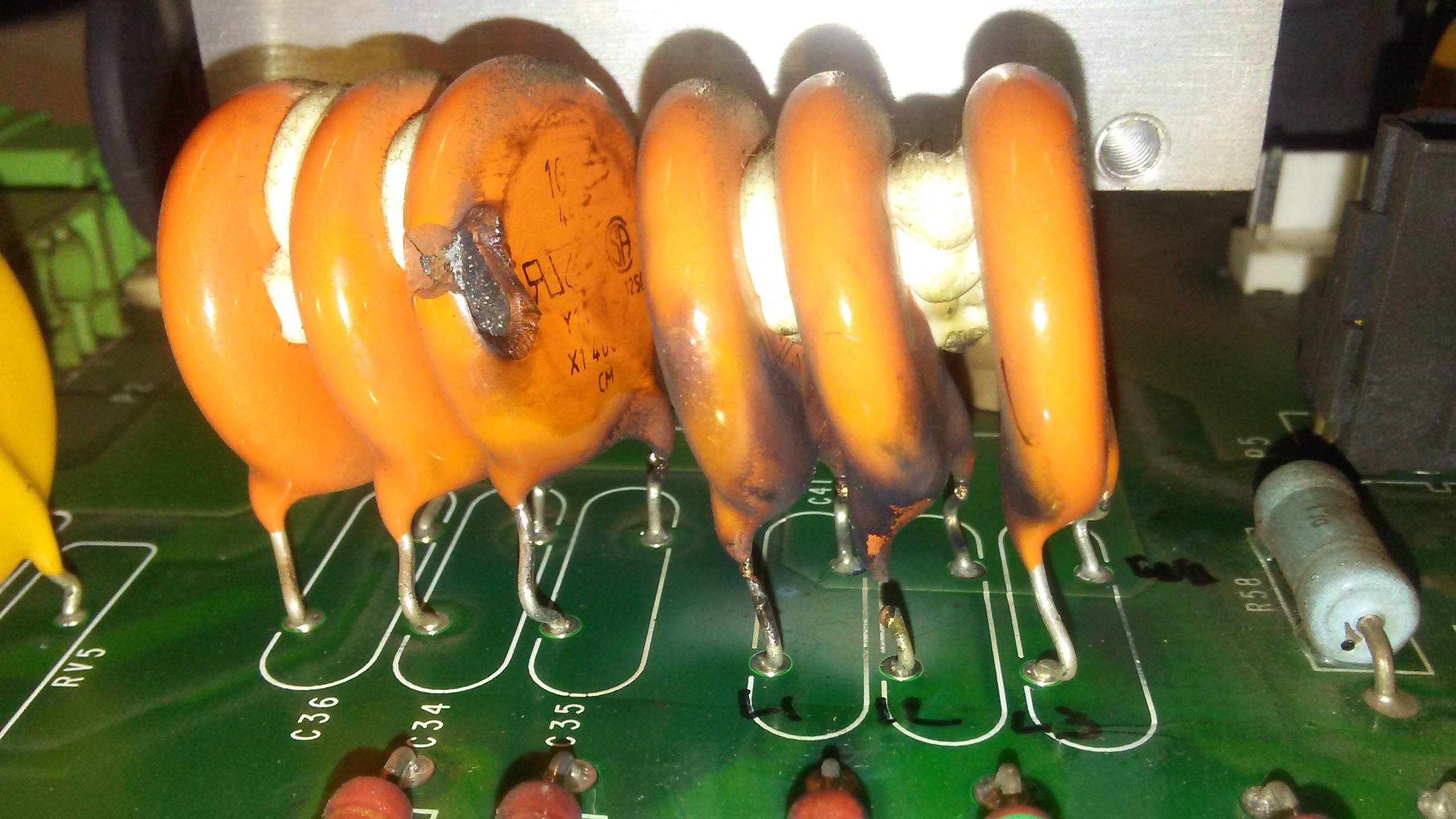
A friend found a distressed Fender Bassman Compact ( solid state ) amp in a junk yard for cheap and asked if I could take a look and make sure all is well. The AC power cable was severely compromised, so the amp hasn't been tested electronically outside of testing the speaker which seems to be fine. In an attempt to ensure all things are safe before trying to power up, I'm checking over the physical build compared to the official Fender schematic.

My question here is this a death cap? See indicated red rectangle below. death_cap.png

I'm used to removing and rewiring the 'death cap' installation on old Fender tube amps, but this amp does not have a polarity switch, rather... simply connected to the chassis from the neutral line.

Since this could be a potentially deadly situation, I wanted to check with smarter folks here so I'm assured of what I'm up against here. If in fact a death cap, how would one resolve safely given the schematic details?

Thanks in advance!
 
Death cap bootlegs ground from the mains neutral (that should be 0V). Plugged into a grounded outlet with three wire line cord the cap is superfluous.

I would lose the death cap and wire up a 3 wire line cord. Then only use it plugged into grounded outlets.

JR
 
The schematic shows a grounded AC plug, it's unlikely that the cap between the neutral and ground will pose any safety issues, unless an AC outlet it's plugged into is mis-wired or someone uses a non-polarized ground lifter and rotates the plug 180˚
 
Last edited:
I don't see how that could cause death. I put a fork in a socket when I was 10 and I'm st-st-st-still he-he-here.

I too have poked knives into wall sockets when I was young - not on purpose, but... Good times!

This aside, since the cap in question here is only connected between neutral and the chassis and not switchable to the line ( assuming the AC cord is properly wired and grounded ), I'm still unclear why this cap was used in this location. Calling it a 'death cap' may be a bit over the top. Hence why I was asking here.

Do you have a complete schematic for this amp? I have one in storage that someone modded a bit but the
power transistors get very hot.

Yes. I couldn't find any free or paid for electronic download copies on the Interweb, but eventually found it ( hard copy only ) for sale from Angela Music.

The copy is just usable. I had to scan it and manipulate in Photoshop to boost the contrast for readability.

https://www.angela.com/fenderbassmancompact1982partslistandschematic.aspx
 
I too have poked knives into wall sockets when I was young - not on purpose, but... Good times!
My first shock was sticking a finger into a lamp socket after the burned out bulb had been removed, I was trying to turn on the lamp. Luckily I grabbed the lamp as I fell back into the nearby couch saving my mother's precious lamp. I am glad our mains voltage is only 120VAC. o_O
This aside, since the cap in question here is only connected between neutral and the chassis and not switchable to the line ( assuming the AC cord is properly wired and grounded ), I'm still unclear why this cap was used in this location. Calling it a 'death cap' may be a bit over the top. Hence why I was asking here.
The more fitting name for it is "stinger cap". Back when this amp was designed there were probably ungrounded outlets that would not ground bond the chassis (like my house still uses), or the all too common used of cheater plug adapters. The bootleg ground cap between chassis and neutral could be somewhat quieter.

JR
Yes. I couldn't find any free or paid for electronic download copies on the Interweb, but eventually found it ( hard copy only ) for sale from Angela Music.

The copy is just usable. I had to scan it and manipulate in Photoshop to boost the contrast for readability.

https://www.angela.com/fenderbassmancompact1982partslistandschematic.aspx
 
The more fitting name for it is "stinger cap". Back when this amp was designed there were probably ungrounded outlets that would not ground bond the chassis (like my house still uses), or the all too common used of cheater plug adapters. The bootleg ground cap between chassis and neutral could be somewhat quieter.

JR

Ah, this makes sense! Thanks JR!
 
Note: these stinger caps need to use special capacitors that are engineered to fail open circuit JIC the neutral gets energized.

"X" rated safety caps are engineered to fail as a short circuit to open the fuse. "Y" rated caps are engineered to fail as an open circuit.

There are X1/Y1 and X1/Y2 rated for dual use.

iINBo.jpg


Here are some caps on a 480V bus and I read what looks like X1 400 on the smoked cap. It looks like it failed short circuit as advertised.

JR
 
I follow lots of guys on youtube who do restorations and repairs of all kinds of equipment. Mr. Carlson will often replace a "death cap" with an X1/Y2 cap.

Other guys like Terry at D-Lab just remove the death cap, install a proper grounded 3-prong mains cord and call it a day.

Other guys who deal in lots of theory not only recommend always using X1/Y2 caps on the mains, they often recommend using THREE safety caps. One across the hot and neutral lines. One from hot to ground, and one from neutral to ground.

So what's the deal here?

Yep, I've seen that configuration too and seen Mr. Carlson's videos. I'd be interested in hearing folks opinions concerning this sort of configuration too.

In my case here, taking the cap out seems like the easiest path, but wondering if that will cause added noise? In addition, the cap that was / is in place atm isn't a safety cap as far as I can tell. Seems like a common NP cap.

IMG_1993.jpg

The above aside, a .047uF safety cap seems to be a rare beast for p-2-p applications. I can find .047uF Y2's that are made for through hole applications, but not specifically for a terminal strip application. Although, I have found a couple of examples that have longer leads that probably could be made to work if need be. If I were to replace with a Y2 safety cap, do I need to concern myself with matching the schematic value? If not, how does one identify a properly valued safety cap aside from voltage specifications?

Cheers!
 
Bearing in mind these caps often fail, I would rather not use them at all. If you have a good mains transformer, most of the crap gets stopped by that.
 
IOther guys who deal in lots of theory not only recommend always using X1/Y2 caps on the mains, they often recommend using THREE safety caps. One across the hot and neutral lines. One from hot to ground, and one from neutral to ground.
It's a different concern. Not anymore about providing a pseudo-ground for an ungrounded mains.
It's about EMI/RFI, where the caps to ground prevent CM and the cap across prevent diff mode noise.
Actually if plugged into an ungrounded socket, the chassis ends up energized at half mains voltage.
Stings at 120V, but jolts at 240.

Anecdotically, in the recent Get back documentary, you can see George getting stung when he touches his mic. I guess it wouldn't have happened at Abbey Road.
The 3-capacitor arrangement is very common in modern gear. As you say, it's about EMI being conducted via the power cord. It's primarily there to keep high-frequencies from flowing OUT of the equipment onto the AC power - especially true if the equipment contains a switching power supply or a microprocessor (or anything else with a "clock"). These size of these capacitors is chosen to comply with leakage current limits imposed by UL or other regulatory agencies. If the ground connection is disconnected (either accidentally or on=purpose with a "cheater" 3-2 prong adapter), the leakage current is allowed to be up to 3.5 mA (or 5 mA if a warning label is affixed). 3.5 mA is a very unpleasant but non-lethal shock. Just FYI, the leakage current limit for equipment originally equipped with a 2-prong power cord is only 0.75 mA, which feels like a nearly imperceptible "tingle" to most people. The reactance of a capacitor, or X, is equal to 1 / ( 2 pi x f x C), where X is reactance in ohms, f is mains frequency n Hz, and C is the capacitor size in Farads. Leakage current I then becomes E / X, where E is the AC mains voltage and X is the previously calculated reactance of the capacitor.
 
Back
Top