Bo Deadly
Well-known member
Similar to the other topic about ferrites on output pins, does it not follow that there should be caps and ferrites on inputs as well like this?:
But because I'm just trying to shunt and block RF and not stabilize an output driver I can skip the 39R in parallel?
Is there any issue with running 48V through these?
Of course a transformer would block RF but in my immediate case, that is on a separate board (or mounted on the chassis) so this will block RF on those leads and generally prevent RF from getting past the connector pins.
UPDATE:
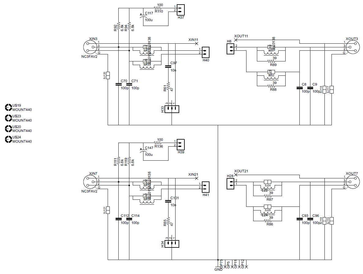
Here is the current schematic:
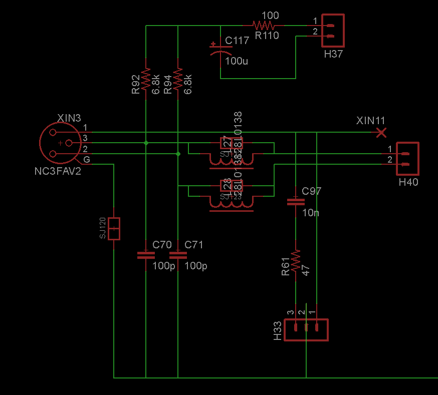
The double square symbols are solder jumps. This is one of about 20 boards that are supposed to be modular so many things are optional (like the 48V which was added after posting the layout).
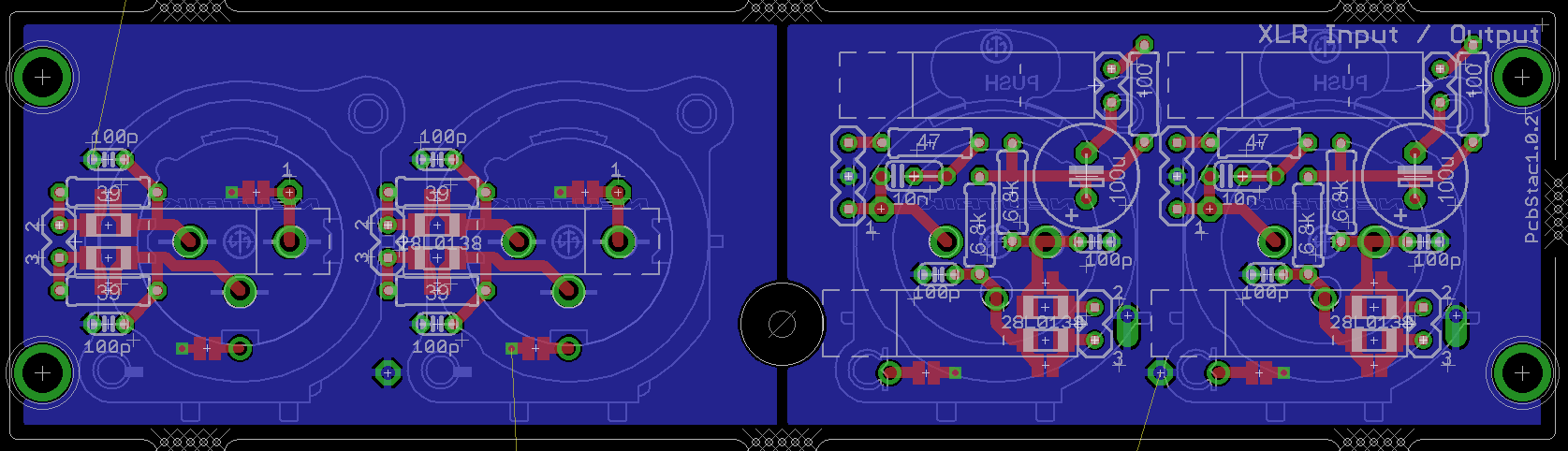
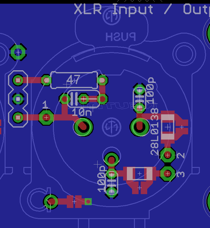
Regarding the layout, the ground plane would ultimately be connected to chassis ground (again this is one of numerous separate boards that have separate ground planes) which is the one trace running off the graphic at the bottom. This is why the 48V ground is separate. The XLR connector is actually mirrored in the graphic but pins 1, 2, 3 are labeled as such. H33 is a header jump for configuring pin 1.
But because I'm just trying to shunt and block RF and not stabilize an output driver I can skip the 39R in parallel?
Is there any issue with running 48V through these?
Of course a transformer would block RF but in my immediate case, that is on a separate board (or mounted on the chassis) so this will block RF on those leads and generally prevent RF from getting past the connector pins.
UPDATE:
Here is the current schematic:
The double square symbols are solder jumps. This is one of about 20 boards that are supposed to be modular so many things are optional (like the 48V which was added after posting the layout).
Regarding the layout, the ground plane would ultimately be connected to chassis ground (again this is one of numerous separate boards that have separate ground planes) which is the one trace running off the graphic at the bottom. This is why the 48V ground is separate. The XLR connector is actually mirrored in the graphic but pins 1, 2, 3 are labeled as such. H33 is a header jump for configuring pin 1.