fet boy

GroupDIY Audio Forum

Help Support GroupDIY Audio Forum:

This site may earn a commission from merchant affiliate links, including eBay, Amazon, and others.
[quote author="Svart"]The strange thing about mine is that with a sig-gen on the input and a scope on the output, the unit works great! I can do 1hz to 500Khz easy, no oscillation at all at any gain right up until clipping. Once I plug in an instrument and plug it into the converter, it oscillates, hisses, hums and generally just throws a tantrum.[/quote]
I probably don't need to tell you this, but that smells like (a) capacitive loading or (b) RF demodulation (through leakage into the output).

JDB.
[so what happens with an instrument at the input and a scope on the output, or a sig gen on the input and the converter on the output?]
 
so what happens with an instrument at the input and a scope on the output, or a sig gen on the input and the converter on the output?

I haven't taken my bass into work yet.. :green:

I probably don't need to tell you this, but that smells like (a) capacitive loading or (b) RF demodulation (through leakage into the output)

I've tried a few things like choking and so forth with slight changes in outcome but for the most part it's somewhat random noise mixed with a little oscillation with a lot of hum. Once I remove the power cord, the hum goes completely away and I get clean signal until the caps power down. Of course I need to scope this while it's happening but I need to either borrow a test rig from work or take my instrument into work. Which I think I will do this week.
 
OK, here they are. These pictures are pretty high resolution, so it may take a while, but the detail is there.
I haven't followed this thread closely but at a first glance I do not see a ground connection for the PSU board. Is this intentionally?

Samuel
 
[quote author="Samuel Groner"]
OK, here they are. These pictures are pretty high resolution, so it may take a while, but the detail is there.
I haven't followed this thread closely but at a first glance I do not see a ground connection for the PSU board. Is this intentionally?

Samuel[/quote]

Indeed!

I think the issues you are incurring may well be grounding ones. Firstly as Samuel pointed out your PSU is just floating, there doesn't appear to be a connection to ground?

Also Fabio's design is not intended to have the the PIN1's or either the input XLR's connected to the ground as you have them, they share a common ground plane and you may well end up running into loop issues this way.

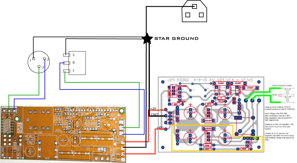
What I have done is just connected PIN 1 of each XLR IN and OUT to my star ground with no GROUND connection on the INPUT or OUTPUT XLR on the FETboy board. Then connect the GROUND on the POWER RAIL on the FETboy to the Stae ground and in turn tied the PSU's ground to the said star ground, which currently you seem to have floating/disconnected.

Try that and report back.

Cheers

Matt
 
[quote author="Samuel Groner"]
OK, here they are. These pictures are pretty high resolution, so it may take a while, but the detail is there.
I haven't followed this thread closely but at a first glance I do not see a ground connection for the PSU board. Is this intentionally?

Samuel[/quote]

You know, I've just been thinking about that. And it maybe still be my misunderstanding of PSUs. I'm not sure how I would ground it.

This picture shows what my psu is.

http://fucanay.fischerworks.com/diy/Fetboy+24+48fromGreenPSU.gif

Maybe someone could explain how this works for me. I have 2 wires coming from the transformer and going to the two AC legs of the bridge. The positive side is going toward the regulator and the other side is going to ground because I left all of the parts outlined in yellow other than the green line that is a jumper to the ground plain. Am I to assume that just like the power transformer being wired in series to get the potential of the secondaries, that the out puts of the bridge does the same thing and therefor there is no real 0V to hook to the star ground?

I think I tried to hook that to the star ground and blew up the fuse, so I know I'm doing something wrong, but I don't really know how to do it right either, I guess.

Matt
 
[quote author="matta"][quote author="Samuel Groner"]
OK, here they are. These pictures are pretty high resolution, so it may take a while, but the detail is there.
I haven't followed this thread closely but at a first glance I do not see a ground connection for the PSU board. Is this intentionally?

Samuel[/quote]

Indeed!

I think the issues you are incurring may well be grounding ones. Firstly as Samuel pointed out your PSU is just floating, there doesn't appear to be a connection to ground?

Also Fabio's design is not intended to have the the PIN1's or either the input XLR's connected to the ground as you have them, they share a common ground plane and you may well end up running into loop issues this way.

What I have done is just connected PIN 1 of each XLR IN and OUT to my star ground with no GROUND connection on the INPUT or OUTPUT XLR on the FETboy board. Then connect the GROUND on the PSU on the FETboy, which is in turn tied to my star ground as is my PSU's ground, which currently you seem to have floating/disconnected.

Try that and report back.

Cheers

Matt[/quote]

So, what you're saying is that on both XLR input and output (in my case TRS output would be sleeve) Pin 1, go to star ground. Leave nothing connected between the fetboy board pad 1 (input and output) and the XLRs.

Then take the PSU ground from the GND pad on each channel on the Fetboy Board and send that to star ground also?

I'll try this later today and report back. If it works, I'll throw up a diagram to show others how to do it.

Thanks Matt

Matt
 
Matt, did you solve your PSU ripple problem?

I'm going to try your PSU without a PeterC board using just your schematic and point-to-point. I wonder if that's a good idea?
 
Matt A Freaking Rules.

Oscillation is gone. Proper grounding helped with that.

All I have left is some hum at 60hz, 120hz and 240 hz as shown below.

fetboy_hum.gif


And here is a sound sample:

http://www.fucanay.fischerworks.com/diy/fetboy_60-120-240_hum.mp3

Anyone have an idea on what causes that?

BTW, I'll post a diagram of what Matt A described later tonight and I'll update the PSU thread too.

Matt
 
I didn't go straight from the PSU board because I thought Matt A said it should be from the ground PAD on the Fetboy boards.

This is the way it is wired, but I'm only showing one channel here.

http://fucanay.fischerworks.com/diy/fetboy_wiring.gif

Matt
 
[quote author="kato"]Matt, did you solve your PSU ripple problem?

I'm going to try your PSU without a PeterC board using just your schematic and point-to-point. I wonder if that's a good idea?[/quote]

I don't know how to use my scope, so don't count on there really being ripple. Maybe now that the damned PSU is grounded my scope will work as I thought it would.

Another thing I need to update is there needs to be a 20R 2 watt resistor on the positive leg of the bridge before it gets to the first smoothing cap to lower the voltage going to the regulator so it won't get so hot.

I still have some hum at 60hz, 120hz and 240hz and don't know what is causing it. If you get yours running and figure it out, be sure to post back.

Matt

I'm going out of town until wednesday, but I'll be checking back then.
 
fetboy_wiring.gif


why has Matt not connected both trs and xlr to the board (pin 1) and also connected pin 1 XLR to common ground with the psu floating? this is a newb question i am wondering about rather than a comment on Matts build.
 
Matt,

Great drawing!

I've made a correction below as you will see the 0V from the PSU goes directly to the star ground not to the FETboy then the Star Ground. I've found this grounding scheme to prove to be the best to date esp. with the FETboys.

fetboy_wiring.jpg


I didn't go straight from the PSU board because I thought Matt A said it should be from the ground PAD on the Fetboy boards.

Yeah, I didn't explain myself clearly enough, I hope the drawing helps and I have updated my text description to help things along.

RE your hum my guess is that it well may be that PSU or power trafo... I quite literally had to move my power trafo out of the rack to attain the least amount of hum possible, that said it was never as loud as the hum you are experiencing right now.

Try the grounding again and then I'd check out your PSU, I think you may well have alot of ripple on their.

While I had limited success with Peter C PSU in that configuration I ended up getting a 24-0-24V torrid and just connected one of the windings with the CT.

Failing that I would use on to Joe's external SMPS with his new fancy Zener regulator. I'm using them on a pair of Neve 1066's I'm racking for client, neat, clean and eliminates inductive hum by keeping the trafo WELL away from the circuit.

why has Matt not connected both trs and xlr to the board (pin 1) and also connected pin 1 XLR to common ground with the psu floating? this is a newb question i am wondering about rather than a comment on Matts build.

Because the PCB shares a common ground plane, linking them in multiple places negates the use of a STAR GROUND where each ground point is ONLY connected at a single 0V reference as illustrated in my drawing.

Hope that helps!

Cheers

Matt
 
Thanks a ton Matt. I'm not giving up on this PSU quite yet. Too much time learning from it to just ditch it. :razz: :razz:


[quote author="matta"]Matt,

why has Matt not connected both trs and xlr to the board (pin 1) and also connected pin 1 XLR to common ground with the psu floating? this is a newb question i am wondering about rather than a comment on Matts build.

Because the PCB shares a common ground plane, linking them in multiple places negates the use of a STAR GROUND where each ground point is ONLY connected at a single 0V reference as illustrated in my drawing.
[/quote]

So, Should we actually be hooking up one side of it? Probably the XLR side's pin 1 and then leave it floating near the board? How does the shielded cable work without connecting the shield at all?

Ok, Lake Tahoe time, back in a couple of days. Cheers

Matt
 
Matt, great documentation impulse you've got. Very helpful in both this thread and your PSU thread. I like the new schematic symbol use for star ground. I think I will use that in my own schematics. :)

[quote author="fucanay"]

I don't know how to use my scope, so don't count on there really being ripple. Maybe now that the damned PSU is grounded my scope will work as I thought it would.
[/quote]

I wondered if you were measuring somewhere in the circuit ahead of the regulators. Post regulator you shouldn't see any ripple I think?

The parts are not too expensive I guess I'll just build it and see.
Thanks again for all your excellent documentation. Enjoy your vacation!
 
@Matt Allison -
I'm thinking of building the mnats version of the fetboy.

I saw your fet biasing procedure which seems to imply that biasing is necessary on the Fabio version due to transistor substitution.

Is the procedure still necessary with the mnats version?
 
With respect to the hum problem: if it's the same in both channels it is likely that there's too much ripple on the supply line. If it's more in the channel closer to the PSU it's probably rather just induced hum. Try rotating the transformer as a first means.

Samuel
 
So, Should we actually be hooking up one side of it? Probably the XLR side's pin 1 and then leave it floating near the board? How does the shielded cable work without connecting the shield at all?

You CAN of course hook it up to the XLR side and NOT to the PCB to still provide a shielded connection (just use some heatshrink around that NC side), I didn't because my cable run is VERY short on a twisted pair and they are VERY quiet even at full gain.

I saw your fet biasing procedure which seems to imply that biasing is necessary on the Fabio version due to transistor substitution.

Is the procedure still necessary with the mnats version?

Since I have NOT built Mako's version I can't answer that. The text does indeed come directly from Scott's article, even WITH his original transistor choice.

The output impedance of the voltage follower is a function 47K resistor on the base of the ZTX653. If this resistor is too big, the output will not have enough drive and will be clipped on one 1/2 of the waveform. On the opposite end of the spectrum, if you make it too small. More power
will be dissipated than needed in the output devices. The value shown provides adequate drive for typical line inputs, with or without the 1:1 output transformer.

The key is to just make sure you are sitting with 12V at the junction of the Darlington pair and 10uF cap.

Cheers

Matt
 
[quote author="matta"] The text does indeed come directly from Scott's article, even WITH his original transistor choice.

The output impedance of the voltage follower is a function 47K resistor on the base of the ZTX653. If this resistor is too big, the output will not have enough drive and will be clipped on one 1/2 of the waveform. On the opposite end of the spectrum, if you make it too small. More power
will be dissipated than needed in the output devices. The value shown provides adequate drive for typical line inputs, with or without the 1:1 output transformer.

The key is to just make sure you are sitting with 12V at the junction of the Darlington pair and 10uF cap.

[/quote]

Thanks for translating for us Matta.
That's a huge help for us newbs.

I recently found this thread: Hamptone JFP trouble There's a helpful post by Chrissugar mentioning picking transistors by beta values - amoung other helpful posts...
 

Latest posts

Back
Top