rockinrob86
Well-known member
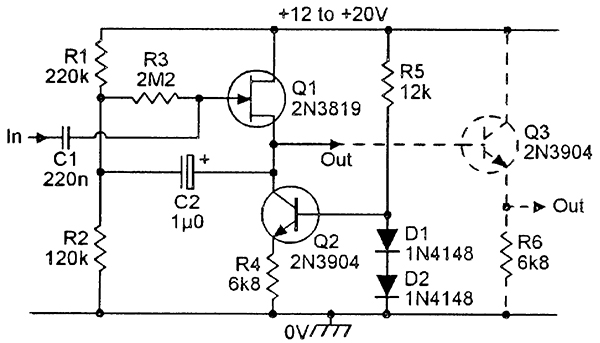
Looking at the ASO98 schematic, at the end of the part in the square, where it says +12db , + - to xformer, how do I calculate what the impedance is?
I'm just guessing that it has been converted in this circuit to low impedance (10K?) and at that point, the two circuits would be feeding the blend knob (which would be 10k to match?), and then from there hit the XLR cable to go to the floor.
At the floor, I would need another gain stage of 12-24db, low impedance impedance input, and output 600 ohms into my -12db insertion loss EQ circuit, before feeding a final makeup stage and a transformer to convert to balanced and go to a mixing board mic pre in.
Does this sound right?
")