follow sinus/triangle with led

GroupDIY Audio Forum

Help Support GroupDIY Audio Forum:

This site may earn a commission from merchant affiliate links, including eBay, Amazon, and others.
Brian Roth said:
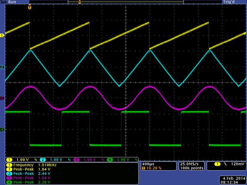
So, look at the LFO on an osciliscope...I suspect it moves between "ground" and +5 VDC.

Bri

nope...

The sine output outputs 0.5V RMS |  1.41 Pk-Pk
901b_outputs.jpg

https://modularsynthesis.com/moog/901b/901b.htm
 
Dayvi said:
nope...

The sine output outputs 0.5V RMS |  1.41 Pk-Pk
901b_outputs.jpg

https://modularsynthesis.com/moog/901b/901b.htm

Which say nothing about the reference...
If the 901b schematic annotation I just look at is correct, the sin output swing around +2V.
Then your sin should be from +1.3V to +2.7V

Best
Zam
 
squarewave said:
The circuits recommended by PRR are clearly just general ideas. In practice you would need to refine the circuit for at least two other reasons:

1) If you're going to get a good range of gain, you're going to need to increase the gain of the transistor and right now that is severely limited by the size of R2. In practice that should probably be more like 220 or even 100 ohms. Otherwise, the LED is just going to vary in brightness a little. You probably want current that ranges from 1mA to 20mA.

2) Theres no way around the rectification (bottom of wave being cutoff) without either adding an offset to the base or lowering the voltage at the emitter. The former is difficult because of requirements from upstream circuitry (as you found out). So lowering the emitter voltage is going to be necessary. But -12V is too much. It should probably be more like -2V. If you only have -12V, then you can make -2V with a voltage divider from ground to -12 and then tap into the base of a PNP with the emitter connected to R2 and then a cap from the base to ground. Adjust the ratio of resistors to get -2V at the bottom of R2. Sorry no schem.

If you adjust things just so, then the LED will smoothly transition between completely off and bright with each sweep of the sine wave.
Your circuit sadly does not work, there is still the offset current traveling back to the input.

But I have found the solution in an old book from the 70’s. All I missed was a resistor.

Thank you for all that helped me in the process. I really appreciate your help.
 

Attachments

  • 2019-10-07 21-25-19-1.jpeg
    2019-10-07 21-25-19-1.jpeg
    665.4 KB · Views: 16
Still guessing what "MOOG Modular" is:

The 901 LFO does indeed have 0.5V output from 1.5k source.
http://moogarchives.com/901d.gif

(As an ARP-survivor, this seems odd. ARP gave a good 10V sweep to suit 1V/oct audio VCOs/VCF.)

Power was +12V, gnd, -6V, -10V. (ARP was all +/-15V.)

The low voltage and high impedance suggests a more elaborate design.

However the later 15, 35, and 55 MOOGs have different module numbers, and may work different; too much for me.
 
Raining.

Add an opamp. Not fussy; neither is the NPN transistor. While I show using the MOOG's negative 6V rail for the opamp, it can probably be powered from Gnd instead. Other power from +12V.

Rtrim makes the MOOG's small wave bigger, trim so it goes solid-bright and full dark (so it looks good). R60 may be changed if the LED average brightness is blinding or dim.

At power-up it will be slow (20-30 seconds) to stabilize because of the long time constant to pass low-low frequency. If you "never" use the slowest rates (12 second cycle), both caps may be 1/10th size to speed cold-start.

For better contrast, put a resistor like R60 ~~1K across the LED. This makes the dim-swing dark.
 

Attachments

  • Dayvi-42-c.gif
    Dayvi-42-c.gif
    23.1 KB · Views: 15

Latest posts

Back
Top