G-PULTEC problems, please help!

GroupDIY Audio Forum

Help Support GroupDIY Audio Forum:

This site may earn a commission from merchant affiliate links, including eBay, Amazon, and others.
Hi there,
i also follow the thread and several people wonder about the voltage differences with the g-pultec trafo. The reason is the Uo voltage (without load) which is 248V on this 220v/0,1A model. If there are differences 253V/259V/... this can be caused by tolerances by the measuring tool or over-/undervolted mains in the European power system. The 220V are the value which can be recieved by loading the trafo with 0,1A. Loading it with less than 0,1A means the value will be a little bit more than 220V. Stressing it with more than 0,1A will kill the trafo. It will get hot, melt and short. This model is to be used in stereo and mono builds but for mono builds you have to switch the 3k3 resistor. 18k 10w like firfe mentioned is a good value to get it down to the 250v tube voltage. I also thought about making a trafo for mono builds but switching the resistor just does the job.

- Don -
 
Hey Guys, i hope somone can help me because i am rather confused.......

For measuring the voltages of the GPultec, i have found info but it assumes that the person knows a bit about electronics which i only know a limited amount. I am a good builder and have built a Neve 1290 clone and the GSSL with SC mods so i am capable.

But where do i pull the ground from on the board to measure the AC voltages?

"Who" (the guy's name) has stated here:

If the trafo is ok you can measure the high voltage most easy at the 3k3 2W resistor legs. The first leg should have around 350v rectivied and the second leg 250v.
The second point to measure is the outer leg on the 10u 25v cap or the outer leg of the 470R resistor between the cap and fuse holder.
You should get out 6,3v there. The minus pole of the measuring tool goes to ground. 


But "Frazzman" comments confuse me:

On second check... scratch what I said in my previous post about the measurements being off between the working and non working units.

I stupidly forgot that I didn't have the PCB linked to ground so my measurements referenced to chassis ground where off when making comparisons between the two units.

Once I had the non working build pcb tied to gnd (as per the working unit) - I was able to replicate pretty much the exact same voltages between each unit (referenced to ground on both the working and non working units).


Frazzman was getting about 50V from the 3k3 Resistor legs, which is close to what i'm getting (with going to chassis/Mains ground) , i get 59/60V from that (CHECK THE LINK IN THE PIC BELOW), but i don't get what he means by tieing the PCB to ground? Is he talking just about measuring from PCB ground and not AC/chassis ground? Or is there somthing i'm missing?

https://docs.google.com/file/d/0BzCEO-3AWPiebGpZWHE1bkNtMGs/edit?usp=sharing

Could someone clearly tell me exactly which points on the board i need to measure including both taps of the multimeter, i.e wher to take ground from......

Thank you so much for your help

 
Ok, i'm guessing you do measure from Mains ground, but when i do i seem to get 60-70V literally all over the board and even from the 2ndtransformer's primaries and secondaries, so i'm pretty confused. If i measure the Mains live pin i get bang on 240V so me multimeter is ok.

Confusingly i measured straight after the toroid transformer and im getting a rating of 70 volts (wich obviously seems wrong), i measure it up to the top leg of the PCB fuse and its still 70ish, then after the the signal goes through the fuse i measure the other end of the fuse pin and it reads about 60, i then get that through the whole board pretty much ( i havent measured all points) even at the 2nd TRX pri's & 2nds and even from the xlr pins and filter board...  (all of these with one of the multimeter poles attached to MAINS GRND)

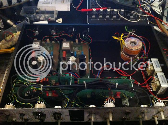
Foolishly i'm not a bread board guy, i build all of my projects direct into the chassis..... so i'm gonna pull the toroids out and see whats up there ( i know i know should have done it to start, but i was hopefull id nailed rhe config...guess not!).....

For the transformers ive got a torodial Amveco 62062-p2s02 : http://www.digikey.co.uk/product-search/en?x=0&y=0&lang=en&site=uk&KeyWords=62062-p2s02

and a Triad fs12-1000 http://www.digikey.co.uk/product-detail/en/FS12-1000/237-1046-ND/242491

The Amveco documentation says: For 230V operation, connect primaries in series by connecting black and red
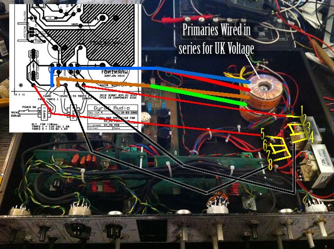
lead wires together and apply 230V across yellow and violet leads wires. So i did just that and soldered the Yellow lead to Mains Neutral, then soldered the Red lead to Mains Live.        I assume this is correct.  I then wired the secondaries in Parallel by putting blue and red togther and then brown and green together. I know nothing about voltage law/theory , i did this because i saw a comment in another post saying to do it and also all pics i can find with this TRX have this config.......

But why am i getting 70v from the secondaries???? is it becuse it wired to the circuit? I'm about to pull them so i guess i'll find out.

##correction#  ok it cannot be right to measure voltages from MAINS GRND.... as even when i pull the torriod i get the same 70V.....Please can somone tell me how to measure voltages on this board i'm stuck.... many thanks
 
Patch said:
Ok, i'm guessing you do measure from Mains ground,
Whatever your idea of Mains ground might be, you might mean safety ground that is always connected to your case ground by a solid connection with a green/yellow wire, capable of standing current flowing at fault condition.
If i measure the Mains live pin i get bang on 240V so me multimeter is ok.
Know what you measure and between which potentials. For measuring mains voltage, set your multimeter for reading AC voltage at a range setting higher than expected, just in case your meter is not auto sensing. From your previous post you seem to be located in europe (please update your profile with your location data. Not only mains voltages differ when asking at an intercontinental forum), so set it to greater than 230VAC. You measure between mains life and neutral (not safety ground).
Confusingly i measured straight after the toroid transformer
from whatever POV after might be, you measure AC voltage across the 1st. transformer secondary connections. This has no reference to mains neutral or safety ground. With your unloaded Amveco 115+115:12V transformer and your higher 240VAC mains you will get a slightly greater than 12VAC, maybe 15VAC secondary readout.
The Amveco documentation says: For 230V operation, connect primaries in series by connecting black and red
lead wires together and apply 230V across yellow and violet leads wires.
correct, assuming you insulated this series connection so it never could touch your case ground or other parts causing a short.
So i did just that and soldered the Yellow lead to Mains Neutral, then soldered the Red lead to Mains Live.  I assume this is correct.
NO! Your description is missing the mains fuse and the mains power switch between the IEC mains socket and the 1st. transformer.
I then wired the secondaries in Parallel by putting blue and red togther and then brown and green together.
Must still be the Amveco transformer you're talking about. If so, this will be correct.
This transformers secondary AC voltage connects thru the fuse on pcb and splits to your 2nd. backwards connected Triad transformer (with both secondary and primary windings connected in series for a 12.6:230V stepup config) for your HT part of circuit and to the heater supply rectifier.
Your quote from member Who refers to a different single transformer.
The reference to 'ground' is the DC reference voltage on pcb. Easiest spot to touch up your black wire multimeter probe might be one of the center pins at the 3-pin molex-connectors [Bal.output], [Bal.input] or [ToFilterPcb]. After your AC voltages from the transformers have passed the rectifiers, set your meter for reading DC voltage when measuring your supply rails (with your red wire probe) in respect to prementioned reference voltage (with your black wire probe).
 
Thank you Harpo for taking the time to answer. Your answer has made things a lot clearer now. Yes i had forgotten to put my location and did it literally minutes before your post.

But unfortunately it seems my Stereo G Pultec is not working after first build, shame i was hoping it might. I guess everyone does!

I tested it and the board does not pass audio, at least the right channel doesnt. i havent tested the Left yet but it also has bad voltage readings like the right so i doubt it will.

The Amveco toroid is outputing 15V from the secondaries so thats fine ( i measured this in AC mode i assume thats right. And i've definitely hooked up the right configuration with no shorts as far as i can see.  But all other readings are off, and i set the meter to DC. They seem really really low, and on both boards. Any Ideas why? or trouble shooting procedures? Any help would be much appreciated.

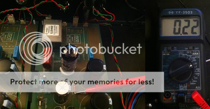
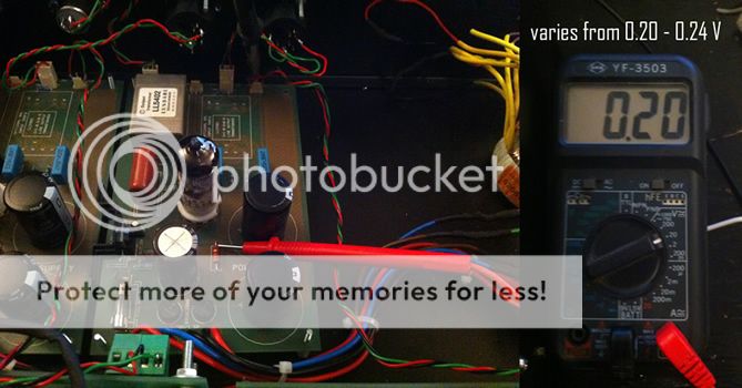
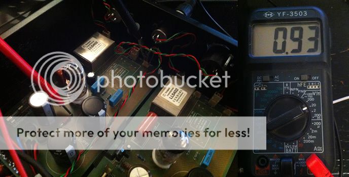
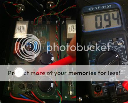
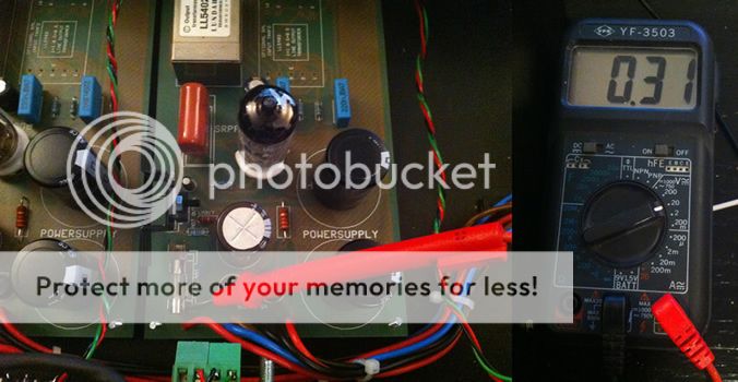
Using your advice Harpo, i connected the black multimeter probe to the GND of the filter connector pins on the PCB. And these readings were made (multimeter reading to the right of each pic is the corresponding reading) :


So they seem totaly off!! :(
 
Hi, i'm connecting the negative (black) to the center pin of the filter connector point on the main PCB. I have tried other points of the ground too like centre pin of the xlr and one of the legs of a resistor by the fuse, but i get the same results, hardly any voltage picked up.

The baords i had soldered about 2.5 years ago and were left around for ages before i recently started up again. I'm wondering if they were touched by people in my flat, maybe got knocked a little.  Maybe the regulators went, or the rectifiers..... would that be a sign of low voltage....

But it strange both left and right board are showing such low values.
 
Patch said:
..But all other readings are off, and i set the meter to DC. They seem really really low, and on both boards. Any Ideas why?
..i connected the black multimeter probe to the GND of the filter connector pins on the PCB. And these readings were made (multimeter reading to the right of each pic is the corresponding reading) :
None of your measurement settings are as from my previous blabla..
Pic 1-4: expected DC voltage in respect to reference voltage about 250V. Your meter setting is for max.20VDC.
Pic 5: expected AC voltage in respect to the other transformer winding side ~15V. Your meter setting is for max.20VDC.
Pic 6: expected DC voltage in respect to reference voltage about 4.78V. Your meter setting is for max.200mVDC.
The polarization of the 10uF cap right side next to the voltage regulator is not visible. Make sure, caps +side connects to the vregs center pin/caps -side connect to the copper flooded reference voltage area. If you got this backwards, expect this cap to be faulty.
Maybe optical artifact, but your transformer secondary fuses on pcb (these are not the mains fuse) don't seem to make contact to both sides of the fuseholder.

Make sure, your meters battery is fresh.
Your black wire probes touchup point for reference voltage isn't visible, but might not make a proper conduction. Maybe solder a piece of wire to the pcb traceside to the copper flodded area (the negative pin side of the big 220uF/350V caps seems a comfortable spot to solder on) and take this wire end for your DC reference voltage.
 
Harpo said:
None of your measurement settings are as from my previous blabla..
Pic 1-4: expected DC voltage in respect to reference voltage about 250V. Your meter setting is for max.20VDC.

I set it to .20vdc because it was the only denominator that i could get a reading on, if i go above i get a zero reading

Harpo said:
Pic 5: expected AC voltage in respect to the other transformer winding side ~15V. Your meter setting is for max.20VDC.

Ah of course, its obvious now you tell me, i need to pop it on the board again to retest

Harpo said:
Pic 6: expected DC voltage in respect to reference voltage about 4.78V. Your meter setting is for max.200mVDC.

again if i push up the meter settings the reading goes to zero

Harpo said:
The polarization of the 10uF cap right side next to the voltage regulator is not visible. Make sure, caps +side connects to the vregs center pin/caps -side connect to the copper flooded reference voltage area. If you got this backwards, expect this cap to be faulty.

hmm checked this and they are in the right polarization

Harpo said:
Maybe optical artifact, but your transformer secondary fuses on pcb (these are not the mains fuse) don't seem to make contact to both sides of the fuseholder.

Yeh it looks like it but i had to shorten one end of the fuse holder to free the trx connection on the pcb. But there is definitely contact.

Harpo said:
Make sure, your meters battery is fresh.
Your black wire probes touchup point for reference voltage isn't visible, but might not make a proper conduction. Maybe solder a piece of wire to the pcb traceside to the copper flodded area (the negative pin side of the big 220uF/350V caps seems a comfortable spot to solder on) and take this wire end for your DC reference voltage.

i havent put a fresh battery but i will, but the meter does tell me when it is running low. Thats a good idea for the DC ref, but did check that i was getting connection to the pin by checking the 'connection beep setting' on the multi meter and connecting the red pole to the ground on the filter board and it was defo well connected. But your wire idea seems more reliable so i'll try it when i get this on the bench.

Just for peace of mind here is how i've wired the TRX. i must admit i wasn't hugely confident that it was correct but from tried to figure it from this thread and googleing,  is this the correct method?

Really appreciate the help, thank you


Patch said:
Just for peace of mind here is how i've wired the TRX. i must admit i wasn't hugely confident that it was correct but from tried to figure it from this thread and googleing,  is this the correct method?
No. The Triad (Trafo 2 from schematic) has to be connected backwards to operate the step up ratio.
Transformers series connected primary windings are between 1/4 and series connected secondary windings are between 5/8.
The 5/8 Triad secondary winding ends connect to the 1st.transformers secondary windings with the fuse on pcb in between.
The 1/4 Triad primary winding ends connect to the '220V Trafo 2' connections on pcb.
Your wiering is 1st.transformer stepped down to about 12VAC and this 12VAC stepped down by the 18.3:1 ratio again, giving about 0.65VAC.
 
Harpo said:
Patch said:
Just for peace of mind here is how i've wired the TRX. i must admit i wasn't hugely confident that it was correct but from tried to figure it from this thread and googleing,  is this the correct method?
No. The Triad (Trafo 2 from schematic) has to be connected backwards to operate the step up ratio.
Transformers series connected primary windings are between 1/4 and series connected secondary windings are between 5/8.
The 5/8 Triad secondary winding ends connect to the 1st.transformers secondary windings with the fuse on pcb in between.
The 1/4 Triad primary winding ends connect to the '220V Trafo 2' connections on pcb.
Your wiering is 1st.transformer stepped down to about 12VAC and this 12VAC stepped down by the 18.3:1 ratio again, giving about 0.65VAC.

Harpo you are the man!!!!!!!! clearly the problem! I'll get this on the bench right now and change it.... i'll post the findings
 
ahh shucks i got excited too quickly.... stupidly i drew the wiring on the pic the wrong way round. I did actually have it wired the correct way to start with.  Woops that was a bit stoopid on my part.  So the problem still remains :(.... but it made so much sense with your calculation...agh shucks

My bad, so this is the way i have it wired.


I now lifted the board and soldered a wire to the ground to do testing with.

I only get 2V from the 250V rail  , then i turned power off, turned back on then i only get 0.08v..... I get absolutely no voltage from  the 6.3v rail. I'm testing all this in DC.

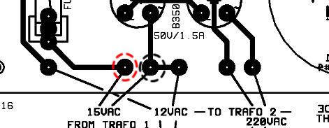
I then switch the meter to measure AC and place the probes here as shown in the pic, but i dont get any reading above zero. Shouldn't i be getting 15Vac from here? Are the toroids still measurable when soldered to the PCB?:


Patch said:
I now lifted the board and soldered a wire to the ground to do testing with.
Be careful at the HT rail spots. When this rail works it will bite you loooong after you powerd off! Discharge the 220uF/350V caps thru a bleeder resistor.
I then switch the meter to measure AC and place the probes here as shown in the pic, but i dont get any reading above zero. Shouldn't i be getting 15Vac from here? Are the toroids still measurable when soldered to the PCB?
Sure. Begin from start. Have the tube fitted in its socket. Measure AC mains voltage arriving at your IEC inlet. Nada? replace blown mains fuse.
Confirm this AC voltage arriving across your 1st.transformer primary windings. Nada? flip the units power switch to ON.
Confirm the 1st.transformer secondary winding arriving with maybe 13VAC at your red/black circled markings (you now have a load connected, so voltage will be lower than your previous 15VAC no load voltage measurement).
Measure DC voltage (about 13VAC*SQRT(2)-2*0.7V=17V raw DC) between the rightmost (in) pin at the voltage regulator and your traceside reference voltage wire. Nada? replace broken rectifier.
Measure DC voltage (about 1,25*(1+1800/470)=6.04V) between the center (out) pin at the voltage regulator and your traceside reference voltage wire. Nada? replace broken LM317 voltage regulator or remove the following short that forces this vreg to shut down.
Heater supply now should be working.

Confirm the 1st.transformer secondary winding arriving with maybe 13VAC at your backwards connected 2nd.transformer secondary windings. Nada? replace broken fuse on pcb.
Confirm 2nd.transformer primary winding arriving with maybe 235VAC back to pcb.
Measure DC voltage (about 235VAC*SQRT(2)-2*0.7V=330V raw DC) between the side next to the rectifier of the 3K3/2W voltage dropping resistor and your traceside reference voltage wire. Nada? replace broken rectifier.
 
Harpo, sorry ive been a bit of a noob and seen i did a silly thing but your help has been very educational and the circuit is much clearer now and procedures too, so cheers for that :)

Ok ive been over it some more and i realized i had done a very stupid thing. On much closer inspection to the fuses on the board i saw that they actualy had burnt out, because to my utter stupidity i had started building these over 2 years ago and had left the boards around until now, but i initialy had put a 400ma fuse on the board....dohh!

So i've replaced them with 2 amp 250V Fuses (closest i have lieing around) and bingo! The valves light up!  On my Right board i get great readings, pretty much 6.3V at the heater and pretty bang on 250v at the HT.  AND IT SOUNDS FREAKING AMAZING!!!!!!!!!  the low end is out of this world!!! big props to you mr.Jacob! amazing unit.

BUT......

Only issue with the right channel is that the 'High cut frequency' selector switch doesnt affect anything when i turn it, it sounds dead...

The left channel is more drastic, it doesn't pass audio and it's very noisy. Readings are off too, i'm getting about 4'ish Volts from the heater and lower voltage on the HT, around the 200v mark.  I will follow the procedure from your inital comment Harpo and see if i can figure out the deal....

But could you tell me a little more detail about how to bleed the big cap with the resistor as now that the board is live i dont fancy giving myself a 300v shock :eek:
 
Patch said:
..i'm getting about 4'ish Volts from the heater..
double check resistor values 470R and 1K8 at the voltage regulator. Might as well be a bad LM317. Make sure the heatsink ist attached in a way that generated heat can be transfered (without overtightening the fixing bolt). Check for noisy output again after you fixed the heater supply.

..i found a good page that explains how to disscharge caps in valve circuits..
essentialy says it all, but with emphasis on 'temporary' bleed resistor. You do the math -consulting ohms law- for required resistor rating with given 250VDC and 10K bleed resistor when the unit is still powered or you simply forgot to remove this bleeder after working on this unit and power on again. A permanent bleeder (maybe 100K/2W) adds 2.5mA to the HT load current and takes a little longer to discharge but might be a safer bet. 
 
WEll turns out everything that was wrong with this build was just avoidable mistakes.

My first issue with the power was just because i had put the wrong fuse on the circuit.  The second issue with the Left channel board was a stupid one again. I flipped the board up and re took voltage readings, and they came out fine, just 0.1 volts difference compared to the second (working) board. so i was about to re-solder the Lundahl transformer, thinking it may have a cold solder joint, when i realosed that i'd actually never even soldered the 220n caps in the audio path. I'd clipped them ready for soldering but hadnt actually soldered them, a good lesson is to recheck the board if you've left it lieing on the bench for 2 years!

So after soldering them down everything works great!! Im astonished at how good this unit sounds, all that i love about tube circuits that big ass bottom end and just that analogue 'je ne c'est quoi' / mojo......WOW!!!!!!!!!! How did i ever live without a unit like this. So chuffed.

Only little thing is the Hi cut frequency selector, i dont hear it making any difference, same for both boards, is this normal? is it doing somthing so suttle im not yet hearing it? i havent done any test tone readings yet.

Again thank you so much  Harpo! :) i need to look into ohm law a bit more me thinks......  And of course Gyraf!

on a side note closest i had for the bleeding cap was a 3k3 2watt, but it worked fine, made me feel soooo much more confident working on the board after seeing the 125volts leak out of the caps that they were storing......im tempted to do a G9 now hihi
 
So I have been trying to understand how to wire up the power with what I got. I could have made it easy on myself by getting the Don-Audio toroid but I bought some parts from a forum member and it came with the FS12-1000 transfo and the Amveco 62062 toroid. This is my first big build so I am trying to wrap my head around the wiring as simple as it may be. I have very little experience aside from a few guitar pedals so I drew this diagram in photoshop to see if I could understand it better. Does this diagram look right? How and where am I supposed to wire the LED? Thanks in advanced for your help.

Alain

EDIT: removed incorrect diagram to avoid it coming up in google searches, will post correct info up ahead. Reply #432.
 

Latest posts

Back
Top