G-PULTEC problems, please help!

GroupDIY Audio Forum

Help Support GroupDIY Audio Forum:

This site may earn a commission from merchant affiliate links, including eBay, Amazon, and others.
pieca said:
Hi everyone,

I'm currently building a stereo gyraf Pultec based on PcbGrinder's CTQ PCB.
There is no fuse on this pcb, and I need to put a fuse in front of my transformer (from don audio)
What is the correct fuse value for 2 boards?

Thanks for your help

I'm using a 315mA in my ctq.. the voltage the fuse covers has to be higher than your local mains supply
 
Hi,

I want to connect a 6,5v jewel light to the 5V output of my toroid transformer (Don-audio).
Do I need to put any resistor or not?

Thanks for your help
 
pieca said:
I want to connect a 6,5v jewel light to the 5V output of my toroid transformer (Don-audio).
Do I need to put any resistor or not?

What Lamp? Could be that it won't be as bright as usual.
 
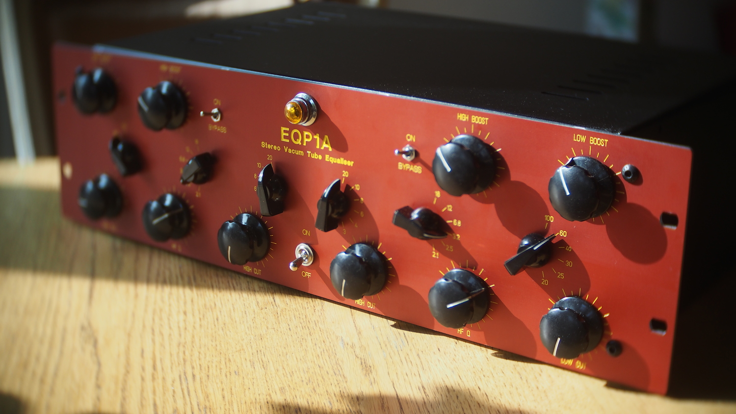
Almost done !

Just have to solder audio in/out, and turn the switch ON…

EQP1.JPG
 
weiss said:
you must have paid much for these rca knobs though...

no, only 12$ for 6 knobs including shipping from china  ;)
MP for seller name

Frontplate made by Frank
Pcb by pcb grinder (CTQ)

 
so after first start-up : no smoke  ;D

6,04 V on the heating circuit
I have 245 V AC on the output of my transformer but 273 V DC at the valve with a 10K resistor (4w)

I'm a noob with the ohm law…
I've a 15k and a 22k resistors (both 4w), which is the better replacement one in order to get a proper voltage at the valve?

Thanks for your help
 
pieca said:
so after first start-up : no smoke  ;D

6,04 V on the heating circuit
I have 245 V AC on the output of my transformer but 273 V DC at the valve with a 10K resistor (4w)

I'm a noob with the ohm law…
I've a 15k and a 22k resistors (both 4w), which is the better replacement one in order to get a proper voltage at the valve?

Thanks for your help

If you measure VDC before the drop resistor, you can check exactly how much VDC you are dropping with your installed 10K resistor.

I will assume its 340VDC before the drop, and you measured 273VCD after, so the drop = 67V.


Ohms law: Voltage(V) = current(I) x resistance(R).


Calculating I

We know the voltage, V (67) and the resistance, R (10K), so we can fill in  ohms law to find the unknown I.

67(V) = I x 10000(R) or 67(V)/10000(R) = I

I = 0,0067 ampere (6,7ma)

Calculating V

For a target value of 250V, you will want a voltage drop from 340 to 250 = 90V.

Calculating R

Now that we know I and V, we can find R

90(V) = 0,0067(I) x R or 0,0067(I)/90(V) = R

R = 13433.


I have tried and had no luck getting close to the expected value calculating it like this, but I am not sure if its because of current draw changes, bad math skills (I hope someone will correct me if thats the case) or something third. I would just install the 15K resistor and see what values I get.

If you try to calculate it, remember to measure VDC before the drop resistor to insert the correct value instead of the 340V

Gustav
 
Thanks Gustav for theses explanations !

So, before the dropping resistor, I have 328V DC

I've switched my dropping resistor for a 22K (metal oxyde 5W) and  now I have 230 V DC for the tube : it seems good !

BUT : my dropping resistor is relatively HOT is 5W sufficient ?

Thanks for your help
 
pieca said:
Thanks Gustav for theses explanations !

So, before the dropping resistor, I have 328V DC

I've switched my dropping resistor for a 22K 5W and  now I have 230 V DC for the tube : it seems good !

BUT : my dropping resistor is relatively HOT is 5W sufficient ?

Thanks for your help

Finding V  - >328 - 230 = 98V

Finding I -> 98(V)/22000(R) = 0,0045(I)

Power = I^2 x R = ?

I dont know if theres a shorter method, but if you plug in the numbers, you should see that 5W is sufficient.

Gustav
 
so, audio test report…

Not so good…

Low cut and boost : ok
High Cut : Ok

But High Boost and HF Q doesn't work at all on both channels :mad:

I'm using a don audio inductor, I don't think there is a cabling problem, and I don't know were to search…
I've also tried in bypass (as in older posts with high problems…)

The level is quite different between bypass and all pots to zero

Any idea?
 
solved!!!

Found on the Gpultec meta tread something about the same issue : filter board and amp board wired backward…

I'm using CTQ pcb. There is a star on the amp PCB and another one on the filter pcb. I've used this star as a mark, but it is not

This thing is huge, and sound really great !!!!!
Flat when pots are zeroed (except a half DB more at 20hz when engaged), but really nothing

Not a single hum or noise issue, I'm happy

Thanks again to Gyraf, gustav, and every one on this forum  :D
 
Have you actually got it working or did you just find a post explaining a similar problem?

As I had a similar problem and it wasnt the solution.
 
APL said:
Have you actually got it working or did you just find a post explaining a similar problem?.

Yes, inverting cabling between amp board and filter board solved my issue
 
good pleased its working. I had similar problems (post 514) and it turned out to be Q pot connections although I had been very confident the connections were good.

Regarding that resistor I couldnt calculate it either. But when first voltage was too high I changed to higher value resistance and got a lower voltage, I plotted values of voltage against resistance and I got a straight line. I read off the required resistor value at the required operating voltage extrapalate if necessary.  well this worked for me

Where did you get those Chinese knobs I couldnt find them when I searched?
 
Very nice unit Pieca! Congratulation :D

I have a similar problem. I've mesured 12vdc on the heater and 340vdc  without a tube in the socket.. In my first test, the tube died few minutes after I turn the power on so I'm afraid to put another tube to take measurment... The first tube was a free tube so it's not a tragedy  ;D but my others tubes are expensive so I don't want to take some risk ;D

Do you measured with a tube in?

It's my first tube diy so I'm a newbie  ;D
 

Latest posts

Back
Top