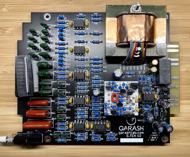
OneRoomStudios said:U1 seems to be getting really hot. I'm guessing there's a short somewhere, but I can't see it. Is U1 on the input or output?
U1 Is the 1246 balanced input buffer which gives a -6db drop in signal.
OneRoomStudios said:U1 seems to be getting really hot. I'm guessing there's a short somewhere, but I can't see it. Is U1 on the input or output?
Bobby Baird said:U1 Is the 1246 balanced input buffer which gives a -6db drop in signal.
OneRoomStudios said:I finally got a chance to finish the opamps and test these out. Unfortunately, only one of them is working at the moment. I must have screwed something up, but I can't figure it out.
The one that isn't working passes signal in bypass, but nothing when engaged. The LED changes from red to green, but no signal. I switched the DOAs, but that doesn't make a difference. I compared the two units, and all the components are identical and in the same polarity. All the opamp power rails have the correct voltage (including DOA), and I can hear the relay activating, so I don't think it's a bad relay. It's hard to troubleshoot much further without a schematic though. Is it possible to get a schematic, or does anyone have any idea of what the issue might be?
As a side note, the one that's working sounds fantastic!
OneRoomStudios said:U1 seems to be getting really hot. I'm guessing there's a short somewhere, but I can't see it. Is U1 on the input or output?
dirty1_1garry said:IMPORTANT MASSAGE!
I added updated assemble manual in a first post of the thread. It's for G.TEN V2 boards revision.
On page 45 it contain step-by-step instruction for checking signal flow from IN to OUT. Can be useful for troubleshooting.
Cheers.
Igor
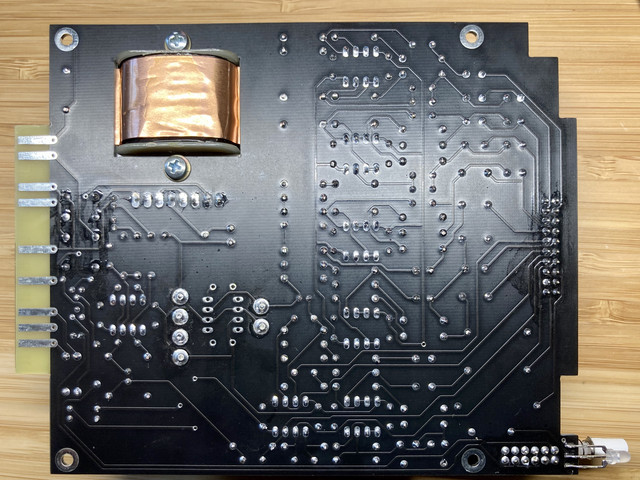
Bobby Baird said:My guess is your IDC male connector on backside of front panel board might be shorting out. Igor is very specific about filing the contacts down and covering it with tape as to avoid shorts.
dirty1_1garry said:You can send me an images of your nonworking unit and I think I will find a trouble.


Bobby Baird said:My guess is your IDC male connector on backside of front panel board might be shorting out. Igor is very specific about filing the contacts down and covering it with tape as to avoid shorts.
SKJGProject said:When will it be available?
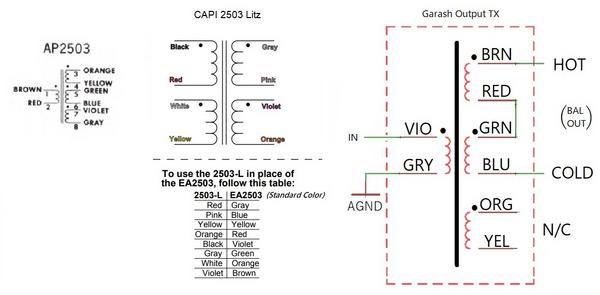
One more comment - on page 43 there is a schematic for wiring 2503 as 1:2. There is a mistake - that's necessary to ground only one unused wire (ORG or YEL), NOT both. If you will connect both you will get a short circuit at one secondary (that's safe for transformer) and you will read -6db instead of +6dB trx gain.


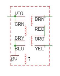
G.TEN V2 is specified for standard 2503 type out trx. On main pcb it is wires as - one winding for primary and two in series for secondary for 1:2 step up ratio, one winding unused.boji said:Do color codes match standard API 2503 colors or are they specific to the Garash TX? Reason I ask is I'd like to use a different TX and checking pcb they seem to be:
Brown and Blue are Hot and Cold outs respectively (edge conn)
Violet is from OPA, TX in
Red and Green are bridged
Grey and Orange are ACOM
EDIT: Granted the 4 windings can be purposed for whichever I/O chosen, but below I think is how 1:2 would be done for use of 3rd party TX's where PCB requires
VIO as Pri in, and BRN as 2ndary out (hot), and ORG tied to ACOM
Anyone willing to review I'd appreciate it, thanks!
Oh, ****!!!Just getting this project on the bench. Igor one of my panels has a misplaced hole for the In / Out button.
DM sent. This was for version 2 boards. Not sure if change to version 3 for the face plate?Oh, ****!!!
I double checked all front panels but the bug still leaked out.
Will send you the new one. Please send me a massage with your address.
Cheers,
Igor
V3 face plate has some changes, not criticalDM sent. This was for version 2 boards. Not sure if change to version 3 for the face plate?