G9 and its frequency response ?? (impedance matching?)

GroupDIY Audio Forum

Help Support GroupDIY Audio Forum:

This site may earn a commission from merchant affiliate links, including eBay, Amazon, and others.
During design, we tried the ECC88 route, but several of our test pilots (in-house engineers) highly preferred the ECC82 output circuit. This, remember, was with the LL5402 output transformer - the OEP options were only added to the project later, to help builders in countries with low Lundahl availability.

Note that the OEP has varying performance in this circuit - some work very well, where other specimens exhibit quite some low frequency loss. It may be due to production variations in primary inductance - the circuit is sensitive to this.

Jakob E.
 
audiophreak said:
Kingston said:
Then I discovered several audio path cap related tweaks
could you expand on this ?

Lately I've discovered just how big (and undesirable) effect caps can have and went into micro optimisation mode with a load of cheap russian PIO caps.

For example C2 is not needed at all. I can't image why it would help even just the DI input, and I don't measure DC anywhere there. Maybe someone knows. Out of the signal path it went anyway.

C4/C5 set up is suboptimal with the two caps in series. C4 only needs to go to the feedback network (could be 1uF as well). And C5 should be connected directly to V1B plate.

C12 has a detrimental effect when paralleled with modern electrolytics (C11). Take it out. I tested this elco+film cap paralleling in a mixer with 7 DC coupling stages in signal path to get a better idea how it acts. A channel with just elcos always sounded better, with somehow better and more accurate transients (which the films are supposed to fix). I would like to know better what is actually happening, but I have no effective way of measuring this.

Minor tweaks, it's shorter audio path with less caps smudging around.

mattyblue said:
Kingston said:
XSM 10k/600. but don't say I didn't warn you.
huh that's odd you get ringing in the hf range. Did you ever try the edcor xsm 2k4/600? I know you tried to hack the 10k/600 to be 2:1 but maybe you don't get that with a with the xsm 2k4/600? Just a theory I guess

I don't know about 2k4/600 and never will. I'm done with edcors. Sound is one thing, quality control is another. I never want to fix a new in a box transformer again.

gyraf said:
During design, we tried the ECC88 route, but several of our test pilots (in-house engineers) highly preferred the ECC82 output circuit. This, remember, was with the LL5402 output transformer

Note that the OEP has varying performance in this circuit - some work very well, where other specimens exhibit quite some low frequency loss. It may be due to production variations in primary inductance - the circuit is sensitive to this.

Jakob E.

I guess those test pilots don't like bass. ECC82 + LL5402  roll-off is very noticeable as already covered earlier, and not dependent on loading conditions or LL5402 variations (of which there should be none).

And yes the OEP option is not optimal either, the two specimens of mine have very different high freq roll off. One is flat to 45khz, the other to 30khz "only".
 
Jakob,
        What should the optimum load be on the output transformers primary and what is the optimal amount of inductance as well? Anyone else is fre to chime in on this as well.
 
Kingston said:
I guess those test pilots don't like bass.

Design was never a question about absolute frequency response -  but about handling detailed information (specially upper midrange) in a musical way. You may very well prefer other sonic signatures - we all have different tastes - but around here there was a consensus that the ECC82/LL5402 was by far the most musical approach to the G9 output stage.

But you're right - The ECC88 type stage as used in the pultec-amp is worth trying if you feel you need something different from the plain-vanilla-taste G9.

Just don't expect it to sound better just because it specs out better on paper..

For example C2 is not needed at all. I can't image why it would help even just the DI input, and I don't measure DC anywhere there. Maybe someone knows. Out of the signal path it went anyway.

If you have no DC across C2, there is a error in your circuit - I suggest you fix this before trying further evaluating and changes, because it will surely affect the unit's way of working.

Look at the G9 schematic http://www.gyraf.dk/gy_pd/g9/g9_sch.gif again: this input topology is not a straight grid-tied-to-ground type - it's bootstrapped from the first cathode (through R8) which is sitting somewhere around at least +55V, so even with the pull-to-ground R7, 47K, you have some +50V DC happening here. Which means that you cannot ditch C2 and hope for the same functionality.

Jakob E.
 
gyraf said:
If you have no DC across C2, there is a error in your circuit - I suggest you fix this before trying further evaluating and changes, because it will surely affect the unit's way of working.

Look at the G9 schematic http://www.gyraf.dk/gy_pd/g9/g9_sch.gif again: this input topology is not a straight grid-tied-to-ground type - it's bootstrapped from the first cathode (through R8) which is sitting somewhere around at least +55V, so even with the pull-to-ground R7, 47K, you have some +50V DC happening here. Which means that you cannot ditch C2 and hope for the same functionality.

But it works, and has no effect on gain or frequency response. I guess it's a safety cap for the DI input only? Wouldn't want 55v on the fingers. the real electric guitar.
 
mattyblue said:
Would a 1:8 ratio input transformer work for our purposes?

Yes, but at the risk of maybe overloading the input circuit at very-loud input signals (condenser mic on bass drums etc.)

Please use the dedicated G9 help thread for questions, this thread is specifically about someone being worried about frequency response.

Jakob E.
 
Hi,

my contribution to the (rather old) topic...
I have two G9's, both with Lundahl at input, but one with OEP at output, other one with Edcor XSM 10k/600. There is a clear difference at low-end and it is quite audible. I did put -30dBu sine to the G9/OEP and -25dBu sine into G9/Edcor in order ot get output levels similar for each gain step. Measured with AP, 40Ohm input output impedance.

Gain steps are 6, 9, 10, 11.
x-axis : Hz
y-axis : dBu

More things to study:
- Hi Freq roll-off with Edcors, it's sounding not so nice.
- Edcors give 45dB gain, OEP's 51dB, I guess that's ok...
- DI, forgot to measure that one

Cheers,

M

G9_FreqResp_Mic_Comparison.jpg
 
Hello!
I use my G9 with only Lundahl Transformers since a while and I often find vocals to sound thin through it. I like what it does to the midrange but it is not usable for about 50 % of the cases. Can this be the basscut issue of the Transformers? What is the best way to test this?

Thanx

Jonas
 
Download RMAA and give is a sweep. Set up a baseline run, output to input of your interface first, so you know what that looks like. Then run it again with the G9 in circuit.
 
i have been running various tests with the G9 (GIX51x) circuit and here are some frequency response related comments, I will endeavor to post data to support these, but I need to do a little more measuring of my recently created test gear to make sure I am posting solid info.

I am interested in the input trafo, termination, impedance and freq resp impact

I have 4 modules under test, they differ by the Value of C2, and the type of trafo's, otherwise identical except individual component variations:
NameInputOutputRatioZi Input trafoZo Input trafoComments
GIX1LL1538LL54021:5Test Driver (>6 ohms) in Mic mode, in Line mode it is 460 ohms Line mode 11500 ohms C2 is 1uf
GIX2LL1538LL54021:5460 ohms 1/(1/470 +1/(4700*2 + 6810*2)) in Line mode Line mode 11500 ohmsC2 is 220nf
GIX3OEP A262A3EOEP A262A2E1:6.45Mic in Mic mode, 460 ohms in Line mode Line mode 19137 ohmsC2 is 1uf
GIX3Cinemag 75101APCOEP A262A2E1:10Mic in Mic mode, 460 ohms in Line mode Line mode 46000 ohmsC2 is 220nf


notes:

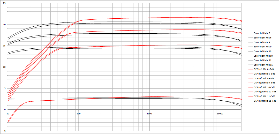
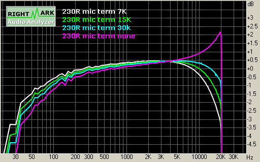
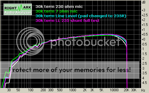
1) The low frequency response is improved by using the Mic mode rather than line mode.  I think that the input impedance of the Mic/Lin pad might be lower than appropriate.  Perhaps lowering the 470 Ohm Shunt resistor and accepting an overall lower Line mode input impedance would extend the low end in line mode.

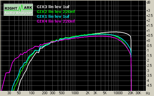
Sweep detail (below):
Line level signal, line mode, output unloaded except normal 10K resistors on schematic

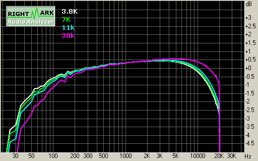
Note high frequency peak on GIX3/OEP input (ringing?)
Note extended low end on Cinemag trafo (Perhaps due to ratio... it appears to be 1:10 as wired).


fr_zps45b2860f.png


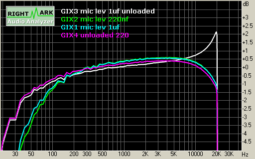
Sweep Detail (below):
Mic level input, mic mode, output unloaded except normal 10K resistors on schematic.

Input from Test Interface, pad creates very low input impedance (>6ohms).
The OEP input transformer rings like a silver dollar.

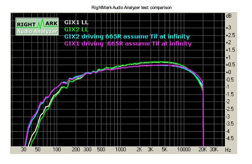
Upping C2 improves low frequency response measurably but only marginally (comparing GIX1 and GIX2 both Lundahl in and Out).  Note that the response of the Lundahls in Mic and Line mode is very similar, whereas the OEP is totally different (extends LF and Rings).  The Cinemag is also similar regardless of mic/line.  Perhaps the OEP needs some sort of termination on the Input trafo?


fr_zpsdd56cdb8.png


Sweep detail, comparing Cap size and output loading.  First unloaded, second 665Ohms. GIX 1 - C2 is 1uf, C2 is 220nf.

Lundahlcomparisondifferentcapsizesanddifferentloadlevels_zps0bacb611.jpg

More to follow...

One note:  The Gyraf schematic calls for a Lundahl 1528, but the GIX calls for a 1538.  Are the specs of those pretty much the same as wired?
 
I should point out that this post is specifically focused on the OEP input transformer and how to get it to behave well in a g9.

Test method here was was to run twisted pair out to a bread board where I could try different terminating loads and Zobels while running RightMark sweeps.

A few more sweeps:

Here sweeping using a simulated 230 Ohm Mic.  Note that the frequency response is extended in all cases, but if there is no terminating load on the A262a3e then the ringing overdrives high end response.  A 30K resistor across the secondary stops this.

Lower terminating resistors extend response a little but have other issues.

fr_zpsade5348b.png


Sweeping in line mode at line levels you can see that lower resistors extend response. 

fr_zps62f6153e.png


More sweeps... But I think the best way to get low end response is to lower the shunt value on the input pad to extend response, simulating a 230 ohm mic ( is this a good compromise value?  or is it too high?  Low?  I figure it is high for an SM-58 and low for everything else?).

Here are sweeps of my compromise (looking for comments if this is the wrong approach.  I change R5 to 235R, I add a 30.1K resistor across the secondary of the input transformer.  With those two changes I get the following response from sweeps (these show both Line Level and Mic Level sweeps)
fr_zps4fe7b579.png


Please comment if you feel this is a bad compromise.  I am trying to get the low end response extended on these input transformers.  A better solution might be to use the Cinemag  or lundhal, but even with these I think the -U-Pad shunt should match the typical mic impedance that the Preamp sees (From my locker these run from 140 ohms to 360 ohms  with an outlyer or two).  They all recommend a preamp input load of >1000 Ohms and some (AKG) >2200 Ohms.  Well the 30000 might be a problem for this with a ratio of 6.45 (squared is 41) so 30000/41  = 731.  Do I need to raise the load resistor to a higher number?  Don't most mic transformer inputs break this recommended impedance spec?

Perhaps I should try terminating with 91K plus.  It will stop the crazy ringing and I can always zobel the peak if I need to.  Or, with the low impedance fix in place, a Zobel network alone might let me kill the ringing and keep the impedance high.
 
As you have already noticed, the changes in input loading have some effect on bass response. But in practice almost negligible. If you scroll back the thread (maybe you did already) you will notice the big bass cut is due to the 12AU7 as output tube. It cannot deliver low enough impedance in this SRPP configuration for the output transformer. Adequate tubes with for the task are 5687 or ECC88 (and variants) for example. I realise this won't help you since you are confined to the GIX51x spec and since heater current simply cannot be increased. And their pinouts are different too.

One another choice would be a different Lundahl output transformer. I forgot the exact model but see what Jonte Knif posted in this thread and you'll find it. But this won't help you either since you are also confined to the PCB pinout and GIX51x size constraints.

These are the 2:1 output transformer choices. If you are happy with less gain, then just use any 4:1 output and bass will happen.

For these reasons I never thought G9 was a good choice to make a GIX51x. Unless one considers these shortcomings "part of the sound".
 
I certainly do consider the shortcomings to be the character of the preamp. There are better designs to be had for all purpose work but I don't think anyone would build a g9 for use in every scenario. The 51x project was meant to capture the original design's sound. Nothing wrong with improving things though. If you make small adapter boards, just about any transformers can be used.
 
Kingston said:
... changes in input loading have some effect on bass response. But in practice almost negligible. ... big bass cut is due to the 12AU7 ... different Lundahl output transformer ... shortcomings "part of the sound".

Thanks Kingston...

Your advice is good and if I want more low end I can add your approach, maybe measure some too.

The output transformers and the drive capability of the 12AU7 have nothing to do with my posts here.  I did read the entire thread with interest.

And I think the exact point of my posts is that the changing of the output tube and the changing of the output trafo Don't have an effect on the "performance criteria I am trying to optimized" (in your words, shortcomings).

The testing I have done shows that there is a lot of bass rolloff unrelated to any output stage component.  To be sure output stage changes are another path, but they don't help if the input stage is killing the bass before it gets to the first Triode.

What I have found is:

The line/mic switch, in combination with the OEP input transformer uses a Shunt of 470 Ohms, changing that to 235 moves the bass rolloff 10-15 hz down.  This is more in line with typical Mic impedances and allows a common termination resistor/zobel pair to function well in both positions.

The OEP has a serious ringing problem, documented elsewhere in this thread, at low impedances and this can be well dealt with using a terminating resistor of 130K, and using a zobel network of 680pf/100k.  This flattens out the top end and helps extend the low end a bit, but the biggest low end extension is from the lower input impedance.

Now you could of course add drive and change the output transformer (although be aware the g9 does lose a little gain lowering input impedance) and extend the low end further, but I think that many of the posts on this thread actually are pointing to issues in the input stage, and trying to address them on the output stage can leave a significant high end peak.  It is also cheap easy and small.

I have also found some issues with the LL1538 input, and the Cinemag Input, but I am not ready to make any suggestions on those yet because my work is still ongoing.

I can post the sweeps for this zobel termination combination if you are interested.

Best Regards

Bruce
 
gemini86 said:
I certainly do consider the shortcomings to be the character of the preamp. There are better designs to be had for all purpose work but I don't think anyone would build a g9 for use in every scenario. The 51x project was meant to capture the original design's sound. Nothing wrong with improving things though. If you make small adapter boards, just about any transformers can be used.

Not suggesting it, but I think the OEP output coudl be made 4:1 with a trace cut or two.

b
 
Back
Top