G9 and its frequency response ?? (impedance matching?)

GroupDIY Audio Forum

Help Support GroupDIY Audio Forum:

This site may earn a commission from merchant affiliate links, including eBay, Amazon, and others.
Ok, here are the results.

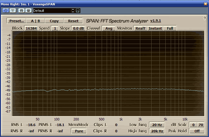
First 3 screens are G9 via mic/line.
The last 3 are G9 via DI.

Input & output transformers are OEP 262.
[G9 bought 2nd hand, no other infos printed on cans].

Audio Precision testing machine [thanks to "playboss" user here, its wonderful  ;D].
Tests gave same results using all output generator impedances [40 150 600] Ohm.
Edit: turned out it was a bad connection on PCB. Impedance now does matter on the bass roll-off.
Same results also with different G9 gain/output settings.
Generator output: sweep with sine wave 20Hz-1000Hz, -9.64 dBm. [tried also with -5dBm, -15dBm, -20dBm, -30dBm, -40dBm, always similar results.. worse with lower signals]
Analyzer input: 100K Ohm.

BTW, the sound of this pre is fabulous.
Just curious if doing mods, swapping input transformers, etc, I'll lose the magic.

res0.jpg

 
Tests gave same results using all output generator impedances [40 150 600] Ohm.

Weird. If the input trannie causes roll-off, then the generator imp really should matter a lot. (surely you didn't have pad on G9?)

Output results show that OEP does in deed have higher inductance than LL5402. Kingston's results show it too.

 
1954U1 said:
Input & output transformers are OEP 262.
[G9 bought 2nd hand, no other infos printed on cans].

you might wanna remove that OEP mu-metal can and check which exact model of OEP A262. Just grip and pull, they should come off quite easily. You might not have the correct model, or it just might be soldered "upside down" (shouldn't be possible when just connecting the dots on the PCB, but let's not underestimate the creativity of a random DIYer). Lets just hope the original builder didn't glue the cans on.
 
Hi guys !
Nice to know that there is still someone trying to solve this problem.
I did a lot of test with my G9, and if I recall I removed one of the 10k resistors loading the 5402 output.
Can anyone try this and report back ?

Cheers
 
Neeno said:
I did a lot of test with my G9, and if I recall I removed one of the 10k resistors loading the 5402 output.
Can anyone try this and report back ?

like I mentioned earlier, I checked it, and as they are only there to dampen the transformer ringing (for certain type of loads, mentioned by Jacob earlier), it did not help the bass response, just as expected.


As a side note, I have some Edcor XSM10K/600 here. They come hardwired as 4:1 ratio (quite a stupid place to reduce manufacturing costs by 10cents), but I'll hack one and wire it as 2:1 and test on the G9 just for kicks.
 
I just did some tests, too.
My G9 is the OEP version.
I hooked up my balanced interface to drive the G9 at line level (with the Line input seleceted on the G9 that should match the impedances) and then from the output back to the line input of the balanced line input of the interface. (10k input)
As expected the bass roll off is there and it doesn't really change with level. Both channels perform the same way so a faulty tranny can be excluded.
Using the direct high Z input doesn't change the freq response at all.
It's strange that I didn't notice this before but I think up til now I just recorded sound sources very near to the membrane thus having a lot off low end due to proximity effect. Maybe on a different pre I would have used a low cut...
I really love the G9. If we just could fix that bass roll off it would be even more usefull!
Let's keep this thread alive, maybe there is an easy fix!
Best,
Stefan
 
I've now read enough about the virtues of the 5687 used as SRPP stage.

Couple of checks,

does R30 alone set the load resistance (zOut?) for driving the transformer?
how do I optimise R29 for the 5687? If I understood correctly this is crucial to run the SRPP balanced and optimal. I guess I want both sides of R30 to be equal voltage, for symmetry (or slightly asymmetric for cool distortions).

Also, many line out or headphone app examples using the 5687 as SRPP recommend running the 5687 with a significantly higher current than 12AU7 or 12AX7 types (more linear, and better sounding apparently). What does this mean exactly, compared to the G9 SRPP, just more B+, and this in turn optimised with the R29 ?

I've no formal education with this so excuse the beginners questions.


[edit]

and dammit, the pinout of 5687 on this PCB is going to be a "slight" problem.  :eek:
 
gyraf said:
1954U1 said:
Ok, here are the results.

If I read the pictures correct, your low end limiting occurs at the input transformer, not from the output stage.

Jakob E.
Yes I am investigating on the input transformers, the frequency response with DI is flat, so no output issues for me.

I've removed the cans, they're the correct OEP A262-A3E.
I'll try to swap the OEP if I find some 1:[5..10] spare transformer here.

Just curious to see if someone with both OEP and Lundahl or Beyer or others as input transformers has done some frequency response tests..
Anyway, no big deal, I'm fine with the G9's sound as is.
 
Right, it has a different pinout!!
OK, that pretty much rules out the 5687.
What about the ECC88? It has a different filament voltage (6,3 Volts) and higher Mu. Would a SRPP stage like the one in Gyrafs Pultec work here, too.
Jakob writes in the pultec section that he uses the ECC88 because of the higher gain and the higher drive capability that help the bass response...
Would the higher gain be a problem in this circuit?
Best,
Stefan
 
steppenwolf said:
Right, it has a different pinout!!
OK, that pretty much rules out the 5687.

Well it's not gonna stop me from trying. It doesn't involve major PCB surgery, just a few cut traces and reroutes. It's still just a dual triode, and not a major change of topology.

It'll need more B+ (not absolutely mandatory, but AFAIK it'll help a 5687 to get more current), but the PSU will handle it with a minor mod for the floated regulator voltage. Then just need to drop a bit more B+ for the 12AU7 feedback stages, but that's just one resistor change.

I can do most of that but I've no clue how to determine the optimal B+ & cathode bias for 5687 in this configuration (or for any tube in general! yes I'm just getting my feet wet), and how to optimise the R29 & R30 for symmetry and optimal load resistance to drive the transformer.
 
About mic/line inputs bass roll-off:

I've an Edcor XSM600/10K and a Carnhill VTB9045.
So I'll try to swap an OEP input transformer, wiring this way:

XSM600/10K
Primary: 1 and 2(center tap)
Secondary: 5 and 8

VTB9045
short pins 2-3, 4-5, 8-9, 6 to ground
Primary: 2 and 4
Secondary: 7 and 10

Now I need only to desolder the trans and redoing frequency sweeps..
one of next days.
 
5687 SRPP does not need more B+ , quite the contrary, this tube is great because of its ability to conduct a lot of current at low voltages.

Traditional SRPP could use same size cathode resistors for lower and upper tube and therefore have equal voltages over the tubes, so, simply check from the tube data sheet curves a bias point (for example 125V and 12mA), the grid/cathode voltage you need for that (something like -5V) and calculate the resistors. (ca 400 Ohms)

This can probably be optimized with different voltage proportions and hence different cathode resistors but it's a good and working starting point.

ECC88 is a traditional and good choice for SRPP. I would also prefer it over ECC82. Work at perhaps 8-10mA and it'll be fine. Higher gain won't hurt in my opinion.

 
Ok!
I'll try the ECC88 with a provisional filament power supply and change the values to the ones used in the Gyraf Pultec SRPP stage that uses the ECC88.
I will report back what it does to the freq response!

Best,
Stefan
 
This time, Edcor XSM10K/600

it's a 4:1 configuration from factory, but I hacked it to 2:1. Thanks to EMRR for the tip that this is actually doable. The two sides of primaries are always hardwired to a center-tap, but it's reasonably easy to separate them with some precision de-soldering surgery.

edcor.png


Sounds great! Edcor quality control is what it is, so I didn't get a curve this good until I hacked another one(but then they're cheap so I can cherry pick). Gain is very much what the OEP and lundahl would be without the bass cut, and this transformer seems pretty good for this application. That bass wobble is interesting. I haven't a bigger/alternative decoupling cap around to check if it's because of the 4,7uF one. The high cut is not only very audible, but the transient response of the +2khz area is a lot softer and more colorful than the lundahl. No surprises there either.

The sound is not neutral by any means, it has "mojo" which is very very different from the lundahl which doesn't really have a "sound". Well it does, but not in the Edcor magnitudes.

Next up, 5687 mods. Might be a few days.
 
Hi!
I just redid some measurements on my G9 as I noticed the bass roll off, too. The measurements I took first were wrong. The new ones show a pretty flat response when using the DI input (maybe -1,5db at 50Hz).
But when using the Line input/Mic input, I get a pretty huge roll off, the one I also noticed when tracking the band. It's defenitivly not an impedance issue.
I tried the Line input, the mic with pad, with 200 Ohms across to simulate a mic, the curve always stays the same way.
Here a pic of the measurement:


@1954U1
What exactly was wrong with your PCB. Maybe I have the same problem as you...

Thanks!
Best,
Stefan
 
Hi Stefan,

This is the history:

1] measured DI input, flat

2] measured Mic and Line inputs with various impedances [40-150-600 Ohms] out of my AP Portable One.
Always same big roll-off starting from 200-300 Hz and boost past 18khz, same as your  curve.

3] dismantled the G9, thoroughly checked and re-spaced all wire connections on PCB, same on wiring to/from the XLRs, switch, pots.
There is one thing to mention: I've bought the G9 2nd hand, and the customs here in Italy are sadly known for often opening-inspecting the shipments
with the care/accuracy of  a bunch of drunk monkeys.
Seen that on the PCB/panel/XLRs interconnections, some tiny wires were sooo near in their terminations.
Cleaned the PCB, both sides, with an air compressor.
Nothing resoldered.

4] Mic inputs frequency response went far far better, and slightly different with different input impedances, as it should be IMO with these trannys.
If someone is interested, I'll post the pics of the new curves.

5] Line inputs still have the bass roll-off.


My theory, now, is that the line input bass roll-off has to do with the combo of resistors onboard and the OEP transformer's primary,
(in mic inputs, no resistors) and that other transformers are less prone to that.. but its just a theory.
Btw I like a lot the color of the OEPs, but likely I'll do, just for sake of curiousity, a test with an Edcor and a Carnhill, as I said above in this thread.


P.S. your italian is almost perfect.. only.. "penso che anch'io abbia", not "penso che anch'io abbi".. but indeed.. "penso di avere anch'io" is more elegant :)
 
Hi!
3] dismantled the G9, thoroughly checked and re-spaced all wire connections on PCB, same on wiring to/from the XLRs, switch, pots.
There is one thing to mention: I've bought the G9 2nd hand, and the customs here in Italy are sadly known for often opening-inspecting the shipments
with the care/accuracy of  a bunch of drunk monkeys.
Seen that on the PCB/panel/XLRs interconnections, some tiny wires were sooo near in their terminations.
Cleaned the PCB, both sides, with an air compressor.
Nothing resoldered.

Ok, i don't totally understand what you actually did. (Sorry if I'm a bit slow...)
1) What did you mean with re-spaced?
2) What do you mean with tiny wires so near their terminations?

It must have an electrical explenation. Capacitive coupling would affect mainly high freq response. What else could have caused that big roll off?
All my connections are soldered with pretty solid wire...
When looking over the schematic, the only components before the DI in is the tranny and maybe the two 6,81k resistors...
What could have caused such problems???
I really can't wrap my brain around that. I just would like to use the G9 as it was meant to be!
I think I might have the same problem as you and I would really want to fix it...
If you could post the new curves that would be really great!
Thanks again!
Best,
Stefan


Yes Stefan I'm a little amazed as you but its not the 1st time I've dismantled a thing, re-assembled, and all went better.  :eek:

1] with re-spaced, I mean.. trying to do more room to the wiring
2] tiny wires and terminations.. better seen on pics, I'll post them later.

and yes me too I know there are only few components before DI, the line impedance resistors R1 R2 R3 R4 R5,  the relay and the transformer..
dont know, my goal was to desolder the input transformers, but in doing the preparatory work, the bass roll-off went away, thats all I know for now..

I suspect that, in my case, it was only a proximity coupling from wires [they were very close... too much close] on pins of XLR panel's connectors.. thats still strange, because its unlikely that both XLRs input connectors do have had the same issue.. but maybe not

Anyway, I'll post in a few hours the new curves and some pics of the G9's inside.
 
Here are the curves of the G9 mic inputs, with different impedance outputs from the sine wave sweep generator.
Generator output always -45dB.
Gain on G9 always the same, output slight dimmed with increasing impedance, as per pics.


40 Ohms
impx.jpg

freq.jpg

settings.jpg


150 Ohms
freq.jpg

settingsm.jpg


600 Ohms
freqn.jpg

settingsc.jpg


Here are some of the "termination" wirings inside the G9 that I've tried to "space" a bit:

81094048.jpg

63617180.jpg

84401234.jpg


The line input bass roll-off is way worse.. but, at this point,
I think that the title of this thread is really right -> impedance matching.
I'm curious to see what will happen after changing the R1..R5 values..
maybe I'll post also these curves if there is interest and if I'll have the time to do the experiment.

All in all I must say that I'm really satisfied with the sound of this G9..
and the wiring "anomalies" are a problem easily fixable, I've bought the G9 2nd hand from a user here at a very friendly price.

Its only this transformer input bass roll-off thing with impedance > 50R..
 
Back
Top