G9 and its frequency response ?? (impedance matching?)

GroupDIY Audio Forum

Help Support GroupDIY Audio Forum:

This site may earn a commission from merchant affiliate links, including eBay, Amazon, and others.
1954U1 said:
I'm curious to see what will happen after changing the R1..R5 values..

Its only this transformer input bass roll-off thing with impedance > 50R..

Well, you should leave R1 and R2 as is. You could perhaps adjust R3, R4, R5 to provide an H-Pad with lower output impedance to present to the transformer primary.

I'm guessing the root issue here is possibly the same as that found with the output transformer... lack of inductance. I've sold all my 1:6.45 OEPs so I can't measure them now, but I did find that the 1:2 models were acceptable.
 
Understood, but in my case, I measured also with my interface directly into the G9 mic input at mic levels. The output impedance of the interface is some 20Ohms but still no better curve.I put 200 Ohms in there to simulate a mic, still the same curve...
About the wiring. The only thing that could have caused the roll off must be located before the transformer. Hence it must have been the cabling between the input xlr and the PCB. In my case, I'm using shielded cable soldered directly to the board, so basically just an extension of the mic cable...
Moreover my input and output xlr are seperated from each other to keep output signals from coupling into input signals.
The output is also shielded cable.
I'm freaking out right now...
 
Well, I suggest you probe the input and move forward through the circuit to find the point of low frequency loss.
 
rodabod said:
Well, you should leave R1 and R2 as is. You could perhaps adjust R3, R4, R5 to provide an H-Pad with lower output impedance to present to the transformer primary.
I'm guessing the root issue here is possibly the same as that found with the output transformer... lack of inductance. I've sold all my 1:6.45 OEPs so I can't measure them now, but I did find that the 1:2 models were acceptable.
Thanks a lot !
Yes R1 & R2 are innocents, it was my destructing compulsion.
Now I am more & more curious to see what will happens with different transformers, also in output.


steppenwolf said:
Understood, but in my case, I measured also with my interface directly into the G9 mic input at mic levels. The output impedance of the interface is some 20Ohms but still no better curve.I put 200 Ohms in there to simulate a mic, still the same curve...
About the wiring. The only thing that could have caused the roll off must be located before the transformer. Hence it must have been the cabling between the input xlr and the PCB. In my case, I'm using shielded cable soldered directly to the board, so basically just an extension of the mic cable...
Moreover my input and output xlr are seperated from each other to keep output signals from coupling into input signals.
The output is also shielded cable.
I'm freaking out right now...
Are you sure that there isnt bass freq resp change, changing mic input impedance?
If its so, I think you do have a faulty transformer, _or_ bad wiring..
If I were you, I'd check the path from the XLR input to DI with a scope or decent bandpass multimeter,.
[like rodabod just said ::)].

 
Jonte Knif said:
5687 would fit in 2-unit, but needs mods in PCB and runs hot.

Both would lead to ca 700 Ohms Zout from the SRPP, which is quite optimal.

I'm trying to optimise a 5687 SRPP here using http://www.tubecad.com/may2000/ article, and I can't anywhere near 700ohm zout (with the functions in the article), unless using an absurdly low (30ohm??!) Rk and Rak. Where did you get the 700ohms?

Jonte Knif said:
Traditional SRPP could use same size cathode resistors for lower and upper tube and therefore have equal voltages over the tubes, so, simply check from the tube data sheet curves a bias point (for example 125V and 12mA), the grid/cathode voltage you need for that (something like -5V) and calculate the resistors. (ca 400 Ohms)

where did you get that 400ohm?

The article suggests me an approximate 200ohm resistor based on the tube datasheets, but again, I only get sensible zout with 30ohms...

[edit]

datasheets told me:
mu = 17 or 18.
rp=1600ohms (another one said 2000)
 
Hi!
Today, I did some extensive testing on the G9. I found out that it's not the output driver that steals the bass freq but somewhere before the DI Input.
Just to clarify:
I didn't do those test because I was bored but because I had a problem while tracking bacause of a noticeable low cut and that's why I started wondering.
The measurements pretty much underlined that.

I measured with my EMU interface that has an absolutely flat freq response. Balanced output impedance is some 100 Ohms, balanced input impedance some 1MOhm. Measurements were done with SpectraPlus.

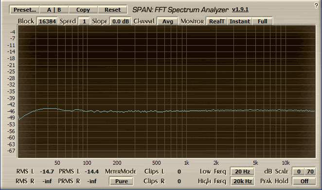
First I tested the freq response using the mic input and monitoring the output.
Source impedance is some 100 Ohms:


You can see the bass roll off and some high frq ringing

Next, I tested the line input with the input resistors giving some 470 Source impedance:


Didn't really change much. Then I added a 470 Ohm resistor to the input pad R5 that would give me some 230 Ohm source impedance:


Notice that the bass respons is better but at the expense of high freq ringing...

I thought maybe this tranny needs low source impedance to achieve good low frew response so I connected the mic input to the headphone driver with some 22 Ohms output impedance:


Now the response is even better, but also even more ringing...

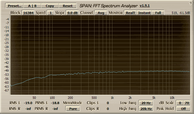
Just for comparison the when using the DI input:


The input tranny seems to be the problem. Both channels behave the same way so it shouldn't be faulty...

Another interesting find:
I looped the input and output of my interface and got a perfectly flat response (of course)
Then I also attached just the G9 input at mic setting (the EMU has 1MOhm input impedance so it shouldn't change much) While still monitoring the output signal of the interface and not! the G9 output. When attaching the G9 the bass freq dropped just like when measuring the unit itself. When disconnecting the G9 the response went back to flat.

I hope somebody else can draw the conclusion as I'm not capable;-)

Another thought:
Could it be a faulty PCB as so many people have the same problems.
I use Gustav's PCB. Maybe you guys that have the same problems could verify that!

Jakob doesn't seem to have any of those problems but then again he makes his own PCB...

Any help is GREATLY appreciated!
Best,
Stefan


Stefan,

your curves gives the same "family" responses as mines..
I think its a transformer impedance issue.

Now we can do 3 things:

1] swapping transformer input

2] changing values of R3-R4-R5

3] investigate on PCB traces

I suspect that working on points 1 [and/or] 2 will do solve [at least partially] the issue..
if not, we've always the 3] point..
are your input trafos the OEPs?

And, I think we must test the inputs focusing mostly on impedance of incoming signal.. or maybe we'll find that less neurotic trafos will be working ok.
 
Thanks for your answer!

1) That might be a good idea
2) Well, thats just help with line inputs, not with a mic, am I right?
3) I don't know if coupling could cause such problems. The mic cable has more capacity then those few cm of traces...

And yes, input trafos are OEPs.

Still, I can't imagine that Jakob wouldn't have noticed such drastic low end reduction in his design and he also uses OEP trannies.
This thread kind of shows that the problem is VERY common.
I mean this transformer is made to be used with 150 Ohms impedance on the primary...

??? ??? ???

Best,
Stefan
 
steppenwolf said:
Another interesting find:
I looped the input and output of my interface and got a perfectly flat response (of course)
Then I also attached just the G9 input at mic setting (the EMU has 1MOhm input impedance so it shouldn't change much) While still monitoring the output signal of the interface and not! the G9 output. When attaching the G9 the bass freq dropped just like when measuring the unit itself. When disconnecting the G9 the response went back to flat.

I hope somebody else can draw the conclusion as I'm not capable;-)

I think this suggests that the preamp is loading down the source at low frequencies. This is most likely due to lack of primary inductance with the OEPs I reckon. I wish I still had some of the 1:6.45 models left so I could test them properly.

Regarding the high frequency ringing (which yes, does get worse with lower source impedance), you could try to help this by fitting a Zoebel network.

Measuring the transformer out of circuit would give a final answer, but it looks to be the source of the trouble to me.
 
rodabod said:
Measuring the transformer out of circuit would give a final answer, but it looks to be the source of the trouble to me.

Yess! Enough of war against impedance matching, lack of inductance, bass roll-off, ringing..
I'll extract the damn iron and do tests with the scope and with the AP, I already know a bit the behaviour of the Carnhill and of the Edcor..
Of course I'll request some help here in understanding results and doing correct setup..  :)
 
I'm trying to optimise a 5687 SRPP here using http://www.tubecad.com/may2000/ article, and I can't anywhere near 700ohm zout (with the functions in the article), unless using an absurdly low (30ohm??!) Rk and Rak. Where did you get the 700ohms?

See the cathode bypass cap? That makes the difference. :)

The prim inductance of those high turns ratio OEP:s is certainly low. The trouble is that they were probably not designed for anything else than speech in mind, or were they? And most mikes these days are around 200 Ohms. Difficult combination for some things to work.

Apart from causing bass roll of the low inductance will also lower bass headroom in a mic head amp. Don't know when you'll run into trouble, but sooner or later with kick drums and certain mikes.


5687 to the rescue!

The mod was a success and thanks Jonte Knif for all the help and suggestions.

I only changed R30 (to 348ohm. it was the closest I had, R29 was already close enough at 475). I got a couple a dB more gain (calculations told me 3dB), and bass is finally there, combined with a hefty bass bump from what I assume is the coupling cap.

lundahl5687.png


I think we can conclude that at least for the LL5402 units that I have, 12AU7 is just not beefy enough. to refresh memory, here's the preamp with 12AU7. Gain is not matched to the above test, but gain doesn't change these curves anyway.

lundahl.png


Only problem now is, I really don't like the Lundahl sound, or actually the lack of it. Sure the transients are clean and there's no distortion, but when I go through the trouble of building a tube pre and sourcing antique tubes, I want to color stuff. There are better (and easier! and cheaper!!) choices for ultra hifi clean.

so back to Edcors it is.

Also back to 12AU7. Why?

1. 5687 run both the heater and B+ supply at their design limits.
2. They run *really* hot, and the PCB layout is just not designed for it. There are several large caps at too close a proximity, and they will die an early death.
3. edcors don't need them, and 2-3dB of extra gain is pointless.


Well there you have it then. In order to fix a stock G9 output stage bass you have to either:

A) get a better suited output transformer.
B) tune the SRPP stage, for example with this rather simple 5687 trick.
 
That´s extremely interesting to read, thanks a lot.
But regarding your statement of colouring the sound I think it´s the real beauty of this design that if handled carefully the sound of this pre is very neutral but if mistreated (higher gain, lower output volume) you get the colouration you want - well, I want at least.
Even the somewhat poor LF response isn´t any problem for me because if I need a rocksolid lowend I´d prefer other pres anyway, even if my G9 had more bass to deliver. But as always, it´s just my opinion, your´s may vary, of course.
 
Those of you who want to use the 5687 for the output tube can use a very similar performing tube called "ECC99" and made by JJ in the Slovak Republic.  It has the same pin-out as the 12AU7.

Kevin Carter
K&K Audio
 
Those of you who want to use the 5687 for the output tube can use a very similar performing tube called "ECC99" and made by JJ in the Slovak Republic.  It has the same pin-out as the 12AU7.
Yes, but the ECC99 is bigger (higher then a Ecc82 so in won't fit into a 2u case...

@Kingston:
You are also using a Lundahl input transformer, right?
What source impedance was used when doing those test?

I really need more base in my G09 to be able to use it on more sources. With my G7 it is especially bad (because the G7 should have a souce impedance round 600 Ohms) so it makes singers sound thin.

Conclusion is that I will try a lundahl at the input but ho can I unsolder those OEPs. Has anybody has some tips?

Best,
Stefan
 
steppenwolf said:
@Kingston:
You are also using a Lundahl input transformer, right?
What source impedance was used when doing those test?

I really need more base in my G09 to be able to use it on more sources. With my G7 it is especially bad (because the G7 should have a souce impedance round 600 Ohms) so it makes singers sound thin.

Conclusion is that I will try a lundahl at the input but ho can I unsolder those OEPs. Has anybody has some tips?

Yes, it was the lundahl input and all those tests, and I tested with 50ohm and 600ohm source impedance.

If you have no de-soldering experience, get some solder-wick and those OEPs will come off easily.
 
Hello... I just bought input and output OEPs 2 weeks ago for my G9. I'm still building it, and now I'm a little bit confused about the way I need to go... so, what do I need to do to get more bass response and get rid of the ringing high end? swap the input trannys? :( change the output tubes for the 12AU7s? well... I have no experience just to see the schematic and take some conclusions that far, and I'm still building it :( so can't test it... so my hand are tight for now and I will follow your indications and experiences ;)
Thanks for all you're knowledge shared here! love DIY!

Eddie ;D

 
Hi!

Be patient just a little bit longer. A few people including me are working on different scenarios...
Up til now in my oppinion the easiest way would be to use the stock circuit with OEP output that seems to have enough inductance and a Lundahl input to achieve a good low end response.
I do loose a little low end in the output section, too, but that is not in same magnitude as the input OEP causes.
I'm building the Gyraf Pultec SRPP stage on perfboard right now (that is VERY similar to the Gp output stage except a different resistor and cap and of course the different tube ECC88).You can't just drop in a ECC88 as it needs different filament voltage.
I will measure with this tube and look what it does to the response. It should have lower output impedance though better low end response...

Best,
Stefan
 
Nice Stefan!! I'll wait for the results of course :) So my input OEP should be changed :S well... talking about the tubes, I'm ordering that from Banzai so should I go for the ECC88, right? better that way :)
I'll keep on waiting, no problem :)
Thanks a lot!!!

Eddie :)
 
Back
Top