You are using an out of date browser. It may not display this or other websites correctly.
You should upgrade or use an alternative browser.
You should upgrade or use an alternative browser.
gar1731 build thread
- Thread starter gar381
- Start date
Help Support GroupDIY Audio Forum:
This site may earn a commission from merchant affiliate
links, including eBay, Amazon, and others.
gar381
Well-known member
biosynth..
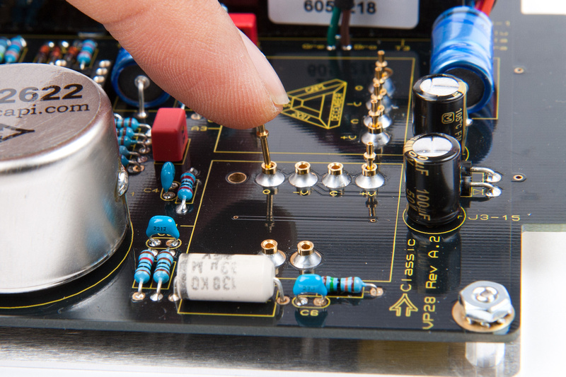
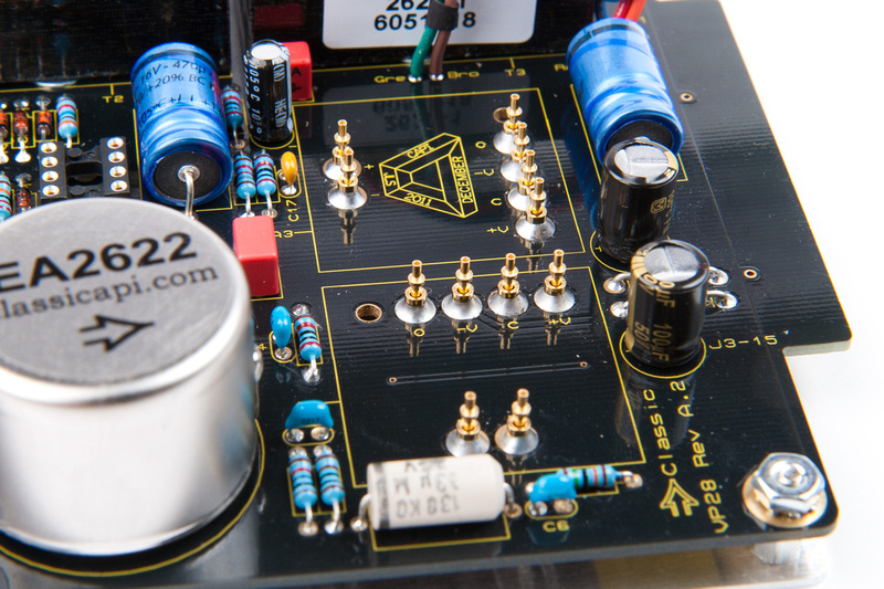
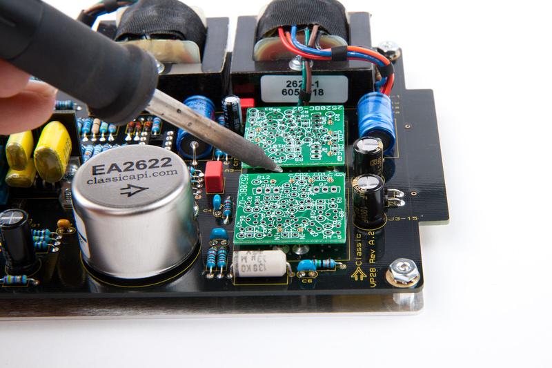
there are lots of good ways. This is one of my favorites
borrowing some of chungers picts from this post:
http://www.groupdiy.com/index.php?topic=48610.msg613811#msg613811


for other ways try google
best
GARY
there are lots of good ways. This is one of my favorites
borrowing some of chungers picts from this post:
http://www.groupdiy.com/index.php?topic=48610.msg613811#msg613811


for other ways try google
best
GARY
gar381
Well-known member
biosynth..
If you use chungers method, Install the pins right after CD1 and CD2 at
the beginning of your build.
The V+, V- and G pins are connected to these caps as they are
for PSU decoupling. No problem If there is a solder bridge to them.
Best..
GARY
If you use chungers method, Install the pins right after CD1 and CD2 at
the beginning of your build.
The V+, V- and G pins are connected to these caps as they are
for PSU decoupling. No problem If there is a solder bridge to them.
Best..
GARY
gar381
Well-known member
Terryb said:Is there a way to test a build without plugging it in to a preamp?
You can build a jig and use an external PSU,signal gen and scope.
(If you are building lots of DOAs this might be worth doing.)
or you can just stick it in a preamp and see if it works.
five fish has a nice jig if you want to go that route but looks
like there is a waiting list..
http://www.fivefishstudios.com/diy-kits/op-amp-test-jig
GARY
Craig32768
Member
- Joined
- Aug 20, 2013
- Messages
- 19
Hi Gary - Built a 1731 plugged into the socket in the VP28 nearest the output transformers. Resistors R14 and R15 burnt out as soon as power on. I've checked for shorts and the diodes appear to be in the correct place. What's the common thing that may cause these to burnout and I'll try and double check it all. Seems to be the same issue that zmgwg was getting but can't see that they posted an update to any issue they found.
Update: Looks like I've got BD139 and BD140 swapped around incorrectly. Will I have smoked these too when R14 and R15 burnt out?
Update: Looks like I've got BD139 and BD140 swapped around incorrectly. Will I have smoked these too when R14 and R15 burnt out?
gar381
Well-known member
Hi Craig
You got a good chance that the "BDs" are OK as They are hardy souls.
Get them in the right holes, replace R14 an R15 then give it a shot.
If things get warm fast shut it down fast then replace the BDs
Best
GARY
You got a good chance that the "BDs" are OK as They are hardy souls.
Get them in the right holes, replace R14 an R15 then give it a shot.
If things get warm fast shut it down fast then replace the BDs
Best
GARY
Craig32768
Member
- Joined
- Aug 20, 2013
- Messages
- 19
gar381 said:Hi Craig
You got a good chance that the "BDs" are OK as They are hardy souls.
Get them in the right holes, replace R14 an R15 then give it a shot.
If things get warm fast shut it down fast then replace the BDs
Best
GARY
Hi Gary - thanks. I can confirm that the BD139 and 140 being the wrong way around were responsible for R14 and R15 burning out. All good now. Thanks for your quick reply. Craig
berkleystudios
Well-known member
how crucial is it to have matching 550c's? if its that big of a deal can someone post a test circuit? i know they can some times be different based on the specific transistor
gar381
Well-known member
Hi Adam
Any cheap multimeter with a hfe socket will work fine.
+/- 5 is close enough but I try to match +/- 2 or better.
even this guy will work
http://www.ebay.com/itm/Pocket-Digital-Multi-Meter-Tester-Ohm-DC-AC-Volt-Amps-hFE-best-for-DIYer-V-/200921289059
GARY
Any cheap multimeter with a hfe socket will work fine.
+/- 5 is close enough but I try to match +/- 2 or better.
even this guy will work
http://www.ebay.com/itm/Pocket-Digital-Multi-Meter-Tester-Ohm-DC-AC-Volt-Amps-hFE-best-for-DIYer-V-/200921289059
GARY
gar381
Well-known member
Note: Dec. 7 2013
MURATA IS DISCONTUNING THE RPC SERIES OF CAPS USED IN THE gar2520 and gar1731!!
The RPE series is being replaced with the RCE series. I will be phasing these in as my RPE
Stock diminishes. I will be using either 50v or 100v based on availability. For you guys buying
Raw PCBs and sourcing your on parts here are some part numbers:
10p 50v.. RCE5C1H100J0A2H03B
10p 100v. . RCE5C2A100J0A2H03B
39p 50v.. RCE5C1H390J0A2H03B
39p 100v.. RCE5C2A390J0A2H03B
47p 50v.. RCE5C1H470J0A2H03B
47p 100v.. RCE5C2A470J0A2H03B
680p 50v.. RCE5C1H681J0A2H03B
680p 100v.. RCE5C2A681J0A2H03B
1000p 50v.. RCE5C1H102J0A2H03B
1000p 50v.. RCE5C2A102J0A2H03B
In a pinch the AVX COG SR15 series...
50-100v 5% with a lead spacing of 2.5mm (.1”)
Should work fine as I have tested these
iampoor1
Well-known member
Could someone send me the build PDF?
Got a few gar1731's for Christmas and my mother accidentally deleted the email with the PDF! ;D
iampoor 1 (at) a t t (dot) n e t
Got a few gar1731's for Christmas and my mother accidentally deleted the email with the PDF! ;D
iampoor 1 (at) a t t (dot) n e t
mus1k_freak
Well-known member
another fun 1731 build 8)


Cosmonaut
Well-known member
Hi, I have bought a gar1731 kit in the black market, and didn´t realized that I don´t have the pdf, somebody?should I contact Gar or Jeff directly?
gar381
Well-known member
Just shoot Jeff an email and he will send it to you Cosmonaut.
GARY
GARY
+1 for smoking one by incorrectly placing the bds into each others slots. I hope I only smoked the 10r's... I don't have the pdf in front of me but is there a chance there is not enough emphasis placed on this step ? Not trying to blame the instructions, they are about as clear and well documented as I've ever seen.  wish I'd seen this thread earlier!
EDIT: upon further review RED BOLD CAPS falls just short of punching my soldering arm. maybe we should be forced to read a schematic for component placement, then we'd pay attention!
EDIT: upon further review RED BOLD CAPS falls just short of punching my soldering arm. maybe we should be forced to read a schematic for component placement, then we'd pay attention!
Amazingly, it's working great now after correctly placing everything and swapping out the burned r's. As much as I've tortured the board with de soldering it probably shouldn't work. Guess those bd's ARE tough!
seems like I can drive it harder than the gar2520 - really "sings" in overdrive. Just like yall said it would
seems like I can drive it harder than the gar2520 - really "sings" in overdrive. Just like yall said it would


