Gates 28 CO New Build

GroupDIY Audio Forum

Help Support GroupDIY Audio Forum:

This site may earn a commission from merchant affiliate links, including eBay, Amazon, and others.
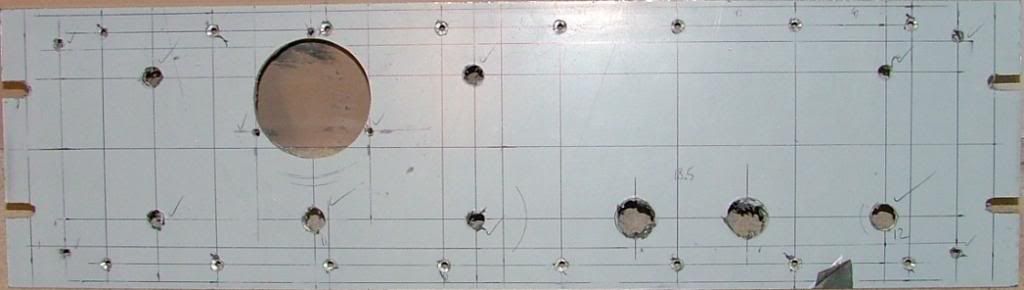
All the holes are now drilled.

I tick off the ones that are finished to size to avoid mistakes, one hole drilled too large and the plate is ruined.
The film looks quite busy by the time its finished.


And here is the finished plate.


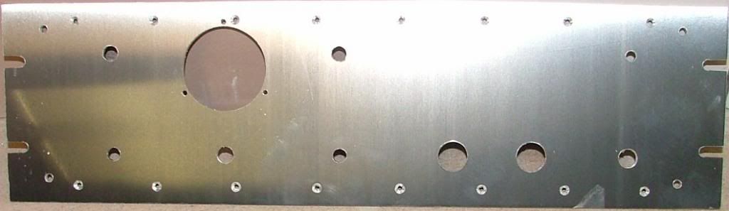
The small 3mm countersunk holes are for the screws which hold the small angle sections that connect the amp to the front plate.

Next job is to fit all the components.

best
DaveP
 
Started the front panel assembly.


The meter is just pushed in for now as it will have to have a new scale fitted marked in dB, that has yet to be worked out.

The input and output pads have to be built and T3 fitted somewhere.

I've also got to cut and fit the angle sections, more next week.

best
DaveP
 
Thanks Nele,

I've now fitted all the angle sections to provide fixings to join the front panel to the chassis.

The screws are also handy fixing points for tag strips and cable ties.


Its a nice snug fit.


Next job is to drill and fit the self-tappers, so that the front can be connected and removed easily.
I'm also working on the graphics for the meter scale, not my strong suit.
Time intensive job is to build the input and output pads which I will be tackling this week.
There's still a lot to do, but the metal work is now finished. :D
best
DaveP
 
Just finished the meter scale graphics.


Now I have to print this off to the right size on a laser printer.

best
DaveP
 
Have been working on the input and output controls.

I've found some 12 way wafer switches from Rapid Electronics.

These can be made to give 12 x 3dB reduction.

The output control is a simple balanced divider having 2 x 25k to match the 50k input TX to the output stage.


The input pad is more complicated as it needs to maintain 600 ohms to both the source and the TX.

This is what I've come up with:-


The resistances are in fact strings of resistors adding up to 600 ohms and they are reverse wired to maintain 600 ohms from both directions whilst giving volume reduction.

best
DaveP
 
Hi Tardis,

The attack time is probably faster than you think, its composed of two parts in any case.

There is the 6J7 attack plus the lamp attack.  The lamps do not light under normal use, only on gross overload, so there is very little thermal inertia to overcome.  My guess would be around the 1-10mS mark.

Incidently, my wife bought me the box set of Breaking Bad for Christmas, how am I supposed to get any diy done now ???

best
DaveP
 
I've been soldering while watching Breaking Bad for the last few months... it's great.
I'm half way through s4.

I still don't get how the compression lamps function. They aren't connected to any control voltage - they are just fully floating between the transformers?
Great looking project, btw!
 
Oh well there's hope then!

You need to read the Wiki bridge article again.

Think of two identical potential dividers in parallel.  At the mid point there is no potential difference between the points, so no signal.

When the two dividers become unequal for some reason there is a difference and they pass signal.

The lamps have the same resistance but one lamp has an extra 7.5 ohm resistor in series.  This means that the lamps receive unequal currents, so one's resistance increases more than the others. This continues until it reaches the same resistance as the lamp plus 7.5 ohm.  (The lamps resistances increase as they pass current)

So you see the mechanism is in place to create compression because as the current increases the signal reduces as the resistances equalise.

best
DaveP
 
We've got a really bad case of "Breaking Baditis" at home now, Wife greets me with "Yo Dude" and I answer "Waasup B**ch".

Anyway BTW.

Fitted the 600:50k OEP Input TX nicely screened in Mu Metal.


I have just finished soldering up the 2 x 12 way input and output switched pads, steps are 3dB.


Fitted the two lamps and a tag strip to start fixing the resistors and other components.


I feel as though I'm on the last lap now.  Next job is to laser print the Meter scale and instal the Meter.

More next week, but I've only just finished season 3  ::)

best
DaveP

 
I was confused on how the compression lamps work because I couldn't see how they were connected to the sidechain.
Now I'm thinking they aren't connected to a sidechain, but basically auto reduce high level signals. Or maybe the lamps have to heat for a few millesecs before the ohms change. Anyway, I understand the "bridge" part.

More next week, but I've only just finished season 3
I really liked the show in s4 and s5. I was watching it on Netflix, and stayed up until 2:30am watching to get to the last episode of s5 - and then realized netflix only had the 1st half of s5!
So I have 8 more episodes whenever they decide to add them
 
Yes, the compression is composed of two separate processes, the main one with a lamp bridge and a minor one with a vari-mu to obtain the release.

The lamp's resistance rises with current and it all works before the lamps even get lit, I put them in holders on the front mainly to show if gross overload was taking place.

best
DaveP
 
Hi Dave,

as always it's fun to watch and read along your working progress.

Are there any plans to publish a "build manual" or something like that?

ROCK-ON!

 
Yes, I'll post the whole works, inc, sound samples, schematic, charts etc.

best
DaveP
 
Next Stage,

It has taken me all evening to get the colour to come out like the screen on our laser printer.  I had to adjust it to look almost red on screen before it came out cream from the printer, did it all in Photoshop Elements and learnt a bit more than I did before!!

Anyway,here's the finished article looking like it should.


Managed to find some tags which lined up with the existing screws and fitted the 7.5 ohm bridge resistors and the diode bridge for the meter.


That all for tonight, should be more to see this time tomorrow.
best
DaveP
 
All the wiring and components are now in place inside the front panel.


The rest of the connections will be made as the panel is connected to the main chassis.  The jack gives an output with just the 6J7 compression and can be used for headphones too, this is exactly the same as the original 28CO, as is the release circuit.


The front now just needs its lettering.
Next week I start connecting it all together.

best
DaveP
 
Also wanted to say that I love these threads and the builds - a real man's work!
P2P power!!
Also, really appreciate the redrawn schematics you been posting in other threads, do you have any more?
 
Thanks Jackies,

I originally scanned in an LA-2 schematic and cleaned it all up in paint, now I have a library of figures that I can cut and paste.

I only have re-drawn schematics for projects that I've completed.  Apart from the BA 6A and SA 39 projects there are these few:-


That should keep you busy for a while ;D

best
DaveP
 
Finally finished wiring in the front panel components.


I moved the second stage Input TX from its original position as it was fouling other parts.  That's what happens with prototypes!

I also decided that it might be a good idea to screen the power cables from the rest of the parts, so quick break to do some more cut and shut.


You can see the TX and its bracket in this shot of the new screen.  So much easier to anticipate a problem than have to return to fix it later after it rears it's ugly head.  When I was younger, I just rushed through jobs in my enthusiasm and ended up with half finished projects.  I might be getting stiff joints (not CJ's kind) and generally deteriorating as I get older, but bizarrely my self discipline is the only thing that's improving!

The final stage is to wire the output to the socket, the grid caps and the second stage screened input cables, all without making a hum loop.  Then a final checkthrough and fire her up.  Hopefully this will all happen next week.
best
DaveP
 

Latest posts

Back
Top