GDIY51X Headphone amplifier

GroupDIY Audio Forum

Help Support GroupDIY Audio Forum:

This site may earn a commission from merchant affiliate links, including eBay, Amazon, and others.
Well, I'm aware of that pot.
With EUR 12 in parts my first thought was too expensive.
Could be changed.

One attractive thing with the "green series": the knob and the jacks have even spaces regarding to the PCB.
 
No,just having some time to do things like DIY..........and a lot of fun too ;D
Believe or not,I'm close to finishing my second dual psu....i need more "juice".
Will post it in the build thread soon.

Cheers,

Udo.
 
Volker,

I think the daughter board's silkscreen is missing
the indentifier for D5 and D6 (1N4148 ?). But that's
no big deal at all. Just for the sake of completeness.

Still waiting for the last parts to arrive...

Carsten
 
Hi Carsten,

they are 1N4148 indeed,you can find them in the orig. schematics page 8 bottom left (Add-On PCB/clip circuit).

Cheers,

Udo. ;)
 
kante1603 said:
Hi Carsten,

they are 1N4148 indeed,you can find them in the orig. schematics page 8 bottom left (Add-On PCB/clip circuit).

Cheers,

Udo. ;)

Thanks Udo. Already stuffed. Was pretty obvious from the parts pitch and from your photos  ;D
Found the other schematics pages just by your hint ::) Didn't pay attention...

Cheers,
Carsten
 
Hey Guys,

I just made up a rough front panel design.
Maybe the other prototype builders want to
double check  ;D

All elements on front are centered. The distances
were measured using the daughter card.
Some dimensions are taken from Volker's Jensamp
front panel.

Best,
Carsten

Edit 08/09/13: Revised FPD-File uploaded.
 
Hi Carsten,

may I suggest one little thing?
It´s the A and B writing on the jacks.This implies there might be two lines or something.
A simple line between them would clearly state that they are paralleled.

Just a thought,

Udo ;)
 
kante1603 said:
Hi Carsten,

may I suggest one little thing?
It´s the A and B writing on the jacks.This implies there might be two lines or something.
A simple line between them would clearly state that they are paralleled.

Just a thought,

Udo ;)

Alright, Udo. I am open to any suggestion.
The front panel needs modification anyway as I didn't consider
the real heights of the headphone jacks and such.

Last parts came in today, so I could finish the prototype.
Unfortunately the pot seems to be scratchy as Udo already
pointed out  :(
I changed R1 to 180K which made the Clip LED barely light
at about +13 dBu.

Was testing with the above mentioned low impedance AKG.

Cheers,
Carsten
 
culteousness1 said:
The front panel needs modification anyway as I didn't consider
the real heights of the headphone jacks and such.
regarding my CAD drawing (based on data-sheets) they should be in one line.

culteousness1 said:
Unfortunately the pot seems to be scratchy as Udo already
pointed out  :(
ok, we should trash this potentiometer.
still haven't had a chance to test myself, and just saw them in a comercial product pic, however ...

culteousness1 said:
I changed R1 to 180K which made the Clip LED barely light
at about +13 dBu.
+13dBu input or output?

great work, guys!
 
Regarding thw scratchy potentiometer:
Are there dc-Blocking caps before and after the pot? I cant find a schematic in this thread, only the schematic with the 2 versions for the mono-switch. And there are no caps after the potentiometer. Couldnt it be that the bias current for the opamp is coming through the poti?

kind regards,
Wolfgang
 
[silent:arts] said:
regarding my CAD drawing (based on data-sheets) they should be in one line.

Yes they are. But the phone jacks need to be moved by about 2 mm upwards in respect
to the X dimension as their outlet isn't centered. Will revise that over the weekend.

Any other wishes for the frontpanel? Colour, LED housing ... ?

[silent:arts] said:
culteousness1 said:
I changed R1 to 180K which made the Clip LED barely light
at about +13 dBu.
+13dBu input or output?

I fed the amp with +13 dBu. So input level.
Level pot fully CW (up to 11 ;D)

[silent:arts] said:
great work, guys!

You are very welcome Volker.
Thanks for providing the Prototype boards!

Best,
Carsten
 
[silent:arts] said:
there are dc blocking caps before, but not after the potentiometer.
Already told you, the pot will get scratchy from NE5532 bias current that a series cap and shunt resistor in front of this opamp for the required DC path to reference voltage should fix. "Wenn die Folgestufe wirklich mit 5532 anfängt, wird das Poti wegen Bias-Strömen schnell kratzig. Ein Kondensator und der dann erforderliche Widerstand nach 0V dazwischengefrickelt und gut iss." The other remarks for the mono implementation and TL07x current drive ability still stand as well.
 
For sure you told me Harpo. Thanks again.
However, the proto-pcbs already have been ordered at that time.

But why does it not scratch in the thousand sold LP units?
This one point I do not but want to understand.
 
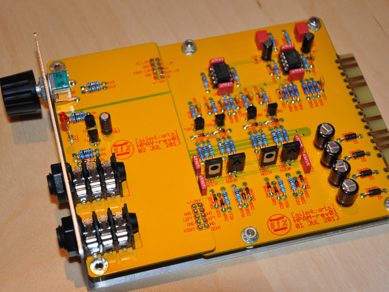
Just to bump this thread, a picture of my prototype:

51x_hpa1.jpg


Any news or ideas for the poti fix?

Best,
Carsten
 
Any news or ideas for the poti fix?

Why not try a Blocking Cap and shunt Resistor after the Poti?

kind regards
 
wolfgang said:
Why not try a Blocking Cap and shunt Resistor after the Poti?

kind regards

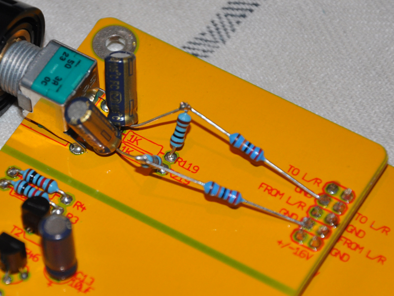
Alright done:

51x_hpa_fix.jpg


Tried 10µF and 220kΩ. With ignoring the rest of the circuit this
should form a HP @ 0.07Hz. Maybe 100kΩ would be more adequate
as the DC isn't fully gone. Also having some small oscillation...

Maybe Harpo chimes in?!

Best,
Carsten
 
Humans win!

Changed the value for the shunt resistor to 4.7kΩ which seems to work.
Maybe some other prototype builders can try and confirm.

Cut off Frequency of this RC is around 3 Hz.
Maybe a higher value resistor is sufficient too.

Cheers,
Carsten
 
Back
Top