Gear porn - cute little IPC tube preamps

GroupDIY Audio Forum

Help Support GroupDIY Audio Forum:

This site may earn a commission from merchant affiliate links, including eBay, Amazon, and others.

b3groover

Well-known member
Joined
Jun 22, 2004
Messages
359
Location
Lansing, MI
Some of you may remember a topic I started concerning building a power supply for some tube mic preamps (http://www.groupdiy.com/index.php?topic=1106). Well, the preamps have arrived!

They are IPC (International Projector Corp.) preamps, licensed by Western Electric. These are the early ones, without the RIAA equalization circuit built-in. They use a UTC HA100X as the input tranny into a 5879 tube to each half of a 12AT7 to a UTC A25 output.

I have a really bad schematic and I'm trying to get my hands on a better one (I know where it is and who has it... getting in touch with him is a different matter.) In the meantime, I tried to fill in the values as much as I could by back-tracing this afternoon. Here's what I came up with:

It's big, so here's a link...
http://www.organissimo.org/pub/IPC-preamp.gif

There are three capacitors which I could not decipher the value of because they are strange caps. Two are those weird mylar square ones and then there is one that looks like a resistor. I assume it is a capacitor because there are 11 caps in the schematic and before I counted this one I could only find 10 caps. Then I realized I had an extra "resistor" and thought, "Well, it must be a cap!" Here's a pic (the red arrow points to the offender):

ipc06.jpg


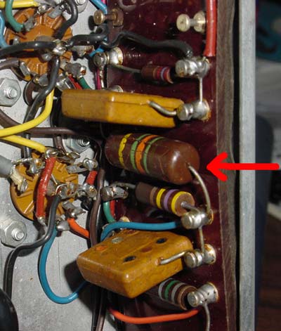
Is that baby indeed a cap? Anyone have any tips on how to get the value of these caps from their markings? Should I worry about the electrolytic cans (there are two)?

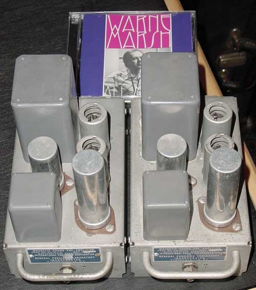
Here is a shot of the two preamps, with a CD in the background for scale.

ipc02.jpg


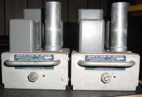
The front of the preamps, with gain control:
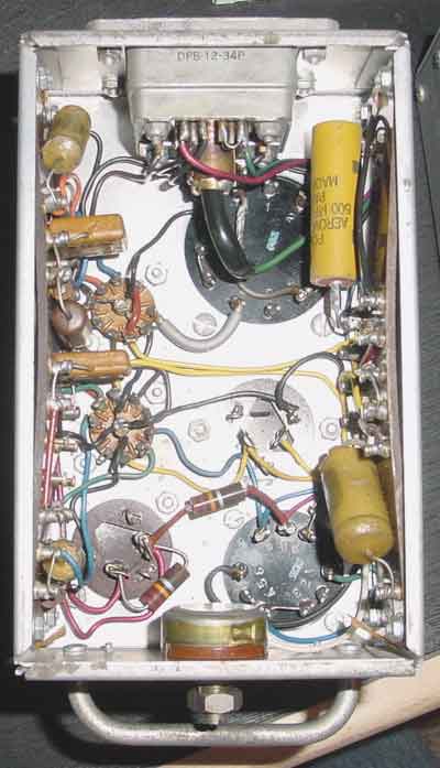
ipc03.jpg


The guts:

ipc04.jpg


And finally, the strange Cannon connector:

ipc05.jpg


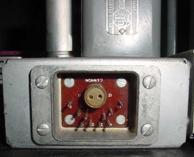
Does anybody know anything about this connector? It would be great to find some, but I'm not holding my breath. I checked the ITT/Cannon site and of course nothing like it exists anymore from what I could find.

Other than the obvious updating of the capacitors, anything else I should worry about? What type of caps would you guys suggest?

Oh, and I think these are wired for 600ohm line input right now. Take a look at the HA100X input tranny:

ipc07.jpg


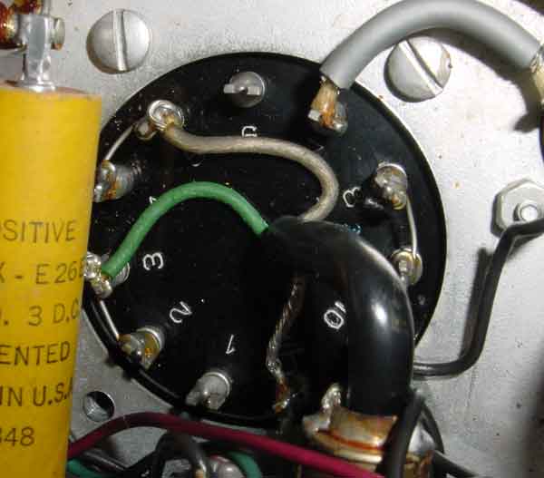
As you can see, the green wire goes to pin 3 of the tranny, which is hooked to pin 2. And the greyish wire goes to pin 5 which is jumpered to pin 4. According to this schematic of the LA2A which uses the same input transformer (http://members.nuvox.net/~zt.robgrow/circuits/la-2a/la-2acir.html, pins 3 and 4 should be jumped together with pins 2 and 5 acting as either side of a 250 ohm load, right?

Fun stuff! I'm still deciding on a power supply.

Here's a question, too. Can I use phantom with this thing?
 
Awesome stuff!
It's got the funk, so you know it's gonna sound killer.
I wouldn't even touch the caps, except the electrolytics.
Darn, someone posted a color code page that had cap color codes also.
That black tubular is a cap, and the postage stamp color dot is a mica cap.
HA100-X , cool!

Someone here posted a real cool color code chart for resistors and caps.
I think I have it somewhere.

cj

From the Radio Designers Handbook:

Dot (1) White indicates RTMA moulded mica cap color coding
Black indicates JAN color coding
Any other color indicates old RMA 6 dot system

Dot (2) First digit of capacitance
Dot (3) Second digit
Dot (4) Class of capacitor
Dot (5) Tolerance
Dot (6) Multiplier

The dot order is 1,2 3 on top row, then 4 5 6 on bottom row, both left to right.

The color codes are the same for resistors, 1 = black, 2 - red, etc

On the tubular,
One of the bands should be further away from the 4 other bands, this band marks the end of the capacitor which lead is attached to the inner electrode

the remaining 4 bands are the first two digits, a multiplier, and the fourth the tolerance, black, 20 percent, brown 1 percent, red 2 percent, yellow 2.5 percent green 5 percent white 10 percent

so for instance, that mica cap has black as the first digit, this means its a JAN (Joint Army/Navy) color code system.

The second dot is brown = 1, the third black = 0,
so the value is 10 times the multiplier which is dot 6, which is red = 100, so 10 times 100 = 1000, which is surley in pico farads, so that is a 1000 pf cap, or .001 uf.
Dot 5 is green, which means 5 percent tolerance.
:guinness:
 
> Two are those weird mylar square ones

giggle. Mylar hadn't been invented yet. Those are Mica. Be careful with them, they are excellent caps.

I know that mike connector well but have not seen one in decades, no clue where to get one today. If you are not restoring the original rack, just nail an XLR to the top.

The schematic suggests a LOT of gain, more than you'd ever want except on a ribbon mike.

The gain control has very little effect, maybe only 6dB. You use it to trim all 40 modules in a desk (or both modules of a stereo pair) to equal gain.
 
Here we go:

32NE0176.GIF

x
x
32NE0179.GIF

x
x
This is when not all the dots are there:
z
z
32NE0180.GIF


Here is where I got this stuff for a more detailed description of how in the heck to figure out these weirdass caps:

http://www.infodotinc.com/neets/book2/3g.htm

see ya!
cj
 
Thank you, everyone! Thank you cjenrick for the cap information. So you wouldn't touch the wax caps? Aren't they the ones that usually get all whacked out of value over the years? I can replace the cans with just regular electrolytics, right?

I can use phantom with these without fear of hurting anything, right?

The fellow I know who has a better schematic emailed me back and said he'd get one to me soon. He also said he has some of these with the original cases which include a power supply, so maybe I'll go that route if the price is right.
 
Have a listen first, before you change Anything.
I have screwed up a good sounding project because i started "upgrading" everything.
Heck, you might even like the sound of those old lytics.

Bring the box up slow with a variac if you have one.
Yes, you can replace the cans with reg. lytics.
They do make those cans still, if you want to preserve the look.
www.tubesandmore.com has them.

Have to look at the schematic to determine phantom possibilities.
hold on.
 
I need to see how the 100_x is wired, and the pins are kind of fuzzy and incomplete on that gif.
I know that transformer inside and out, so I will be able to tell you if you can get away with a little dc on the primary.
That is a two coil construction, so the dcr tends to be pretty well balanced if the winder wasn't out to lunch.
cj
 
OK, it looks like they have that wired for a low impedance mic.
That is a terrible way to run that beautiful transformer, only one half of the primary is used, which is gonna cause an imbalance in the core which means xtra distortion.
Hook pins 3 and 4 togeather, and apply your signal to pins 1 and 6.
This will give you a 600 ohm input.
And you can run phantom no problem into pins 1 and 6 via a couple of 1 percent or better resistyors, 6.8k.
cj
and don't ground the 3-4 connection. :guinness:

err, i just re read your post, looks like they share both coils, so thats cool. It dosent look like it in the pic.
Hey, is that a A-24 on the output?
And how much did you pay for all that iron!
 
Yes, that is an A24 on the output. The HA100x is not represented well on the schematic. So the way it is wired now is ok? Pins 2 and 3 are hooked together for one side of the input and 4 and 5 are hooked together for the other. Pins 1 and 6 are not used. Is this acceptable? What's the impendence, 250?

I paid just over $200 for the pair.
 
[quote author="PRR"]The schematic suggests a LOT of gain, more than you'd ever want except on a ribbon mike. [/quote]

I wonder if these were designed for use as head amps for some kind of tape machine? IPC= "International Projector Corp" =magnetic film soundtrack?? And if so, is the CR network from the anode of the 5879 an equalisation network of some form?

Just thinking aloud...

A neat way to replace top-mounted electrolytics is to carefully unfold the rim keeping the terminal cap in. Diagonal cutters used carefully are good for this. Slide out the innards and remove/dispose carefully. Leave the solder pads connecting to the outer tags. Clean any gunge out of the can. Luckily, modern caps of the values and voltage ratings needed are much smaller then years ago, so the modern equivalent will fit inside the old can with room to spare. Put some insulating sleeving on the cap leads and solder to the underside of the old cap. Make sure the polarity is correct! Fill the empty can with dry and fireproof wadding such as rockwool etc. Then place the top-cap/new capacitor assembly back into the old can. Make sure the leads are well insulated and not touching the sides. Then just re-fold the lip to seal the assembly, and add a little epoxy glue to make a good seal if needed. And you're ready to go! Still looks retro, but you can rest assured that the caps are good.

Nice score- let us know how they go!

Mark
 
[quote author="Mark Burnley"]

A neat way to replace top-mounted electrolytics is to carefully unfold the rim keeping the terminal cap in. ..... ! Still looks retro, but you can rest assured that the caps are good.
Mark[/quote]

Nice tip, Mark. Thanks. I have an application for this!

I'd second the tip about not changing too much. see how it sounds first & if you like it.

Stewart
 
[quote author="Mark Burnley"]I wonder if these were designed for use as head amps for some kind of tape machine? IPC= "International Projector Corp" =magnetic film soundtrack??[/quote]

Bingo! That's exactly what they were made for.

And if so, is the CR network from the anode of the 5879 an equalisation network of some form?

Well, these are supposed to be free from the RIAA equalization that came standard on the later modules. If that is indeed what that R/C network is, I'll probably remove it.

Thanks for the tip on preserving the can cap look! Very handy!
 
Ok, so I finally got a working power supply for these. I changed the filaments to run in parallel, as suggested in this thread:

http://www.groupdiy.com/index.php?topic=1106&postdays=0&postorder=asc&start=0

So now both the 12AT7 and the 5879 are getting 6.3vac for the filament. The B+ I'm giving the unit is about 350vdc.

So here's the rub. I'm not getting any amplication. If I put a line level signal at the input and listen to the output, I can hear the signal (barely) and it sounds fine. As soon as I turn on the power, the signal level drops even more and starts distorting badly. I have two of these and it's the same on each one.

Here's a link to the schematic. It's horrible and I figured out as much as I could: http://www.organissimo.org/pub/IPC-preamp.gif

Ideas? How do I go about checking caps with a standard volt/resistance meter? I'm hoping it's something simple like the cans needing replaced.

I've also noticed that the filaments on the 12AT7 are barely lighting up. In fact, neither tube is lighting much. On my Leslie (the only other tube gear I have experience with) the 12AX7's are lit up like Christmas lights. Shouldn't the tubes in this be brighter?

Forgive my ignorace, I don't have much experience with this stuff.
 
What are the Plate, Grid, and Cathode voltages?

All grid voltages should be zero (+/-100mV): if not, replace the cap that goes to that grid.

All Cathode voltages will be a couple of volts. It is not worth figuring the first two stages, because:

Plate voltage on the first two stages should 1/4 to 3/4 the supply voltage. If it is in that range, it will work, even if not right.

The output stage Plate voltage will always be nearly B+. Get a good reading on the Cathode voltage.
 
Well, I've got some problems. Either there's a lot of bad caps or this thing is hooked up wrong. I'm getting B+ everywhere.

Here are the voltages I measured:

12AT7

pin 1 (plate) = 340vdc
pin 2 (grid) = 333vdc
pin 3 (cathode) = 345vdc

pin 6 (plate) = 349vdc
pin 7 (grid) = 310vdc
pin 8 (cathode) = 343vdc

5879

pin 1 (grid) = 345vdc
pin 3 (cathode) = 345vdc
pin 7 (grid) = 307vdc
pin 8 (plate) = 333vdc
pin 9 (grid) = 345vdc

:cry:

I should add that my power supply is outputing 350vdc for B+.
 
You should omit those dashes before the voltages. I thought you were talking about negative voltages at first.

It sounds to me like you've connected your negative voltmeter lead to chassis ground instead of input (signal) ground. Connect your negative lead to signal ground and take the readings again. The other possibility is that you connected your power supply negative lead to chassis ground and not signal ground; it should be connected to signal ground.

At any rate, your "zero volts" reference point should be input (signal) ground, not chassis.
 
Dave, thank you. I did indeed put the negative probe on the chassis to get the reading.

Now, concerning the power supply negative lead... this is the other side of the B+ output, right? You're saying that needs to connect to the signal ground and not the chassis ground?
 
Ok, connecting the power supply negative to signal negative and I got amplification, albeit badly distorted amplification. However, the measurements are much more in-line with what I should be seeing.

Plate voltages are around 310 and one is around 140 or so (the other side of the 12at7, which makes sense). Cathode voltages are hovering around 1.5 or so. All grid voltages are 0 except pin 7 on the 5879 tube. That pin is reading 40vdc. There's a .1mf cap there, so that's the bad boy I'm going to replace. COOL!

Thank you, PRR and Dave for your helps.

Am I understanding everything correctly? :)
 
The chassis ground is almost always the same as the signal ground.
Connect the pwr supply neg lead to the filter cap tab that has the rest of those ground wires going to it.
350 is might high for those tubes/transformers, but it should drop down once you figure out whats wrong.
Turn it off and ohm out all those old resistors.
There are 220k bleeders in there, but don't trust them. Make sure the caps are discharged.
Ooops! That yellow band is really orange so those are not bleeder resistors.
Check your ground path. It sounds like the pwr supply neg lead is not reaching the signal ground.
 
Back
Top