While it intuitively seems like a DC relay coil would be inherently polarized (like wondering if the actuator would push rather than pull with opposite coil polarity), I have only ever physically encountered two kinds of DC relays that suggested or were marked with polarization: relays with integral diodes across the coil (less frequently, relays with both integral driver transistors AND transient suppression (like Teledyne TO-5 can relays), and relays with specs that called them 'polarized'. The ones I saw specifications for (I had to look them up for someone, and didn't literally have one) that said 'polarized' didn't literally say 'latching', but I think they had high G force ratings. Maybe they latched, also, but the ability to stay closed without contact bounce seemed to be the focus.
Panasonic describes (their) polarized vs. unpolarized relays in this literature, and their focus seems to be on latching types. Single-coil and dual-coil latching types exist (not referencing Panasonic, just in general).
Difference between Polarized and Non-polarized Relays | Automation Controls | Industrial Devices | Panasonic
Some relays are shielded (like on multiplexer cards with several or many). Most of those I've seen (repairs for welded contacts or contact resistance exceeding end-of-life rating) didn't have coil polarity markings, and neither did the circuit hoards, but it might have been desirable to maintain the original behavior. The board layout prevented accidental reversal, and that's a different scenario altogether than incorporating a single relay that wasn't present previously.
'Not liking certain voltage': I often test a relay I haven't found specs for (yet) with a variable bench supply. If I'm lazy and just use clip leads and no transient protection diode, I have seen a regulated supply 'freak out' when the relay is cycled repeatedly. The voltage digital display shows transient voltage changes, and I immediately am embarrassed I was too lazy and didn't think about the power supply being offended by the transients. I usually think driver IC's or transistors and EMI are what the diodes protect. Then I respect the bench supply for a while until I get lazy months later. I should probably make a pair of test clips with diodes soldered so I have no excuse for thinking it's too much work to do a 30 second relay experiment.
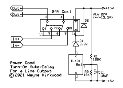
If you do have a single diode across a relay coil, then there is no question at all that the application itself is now polarized.
A DC with too much coil voltage (within 'reason', which might be on a data sheet) applied will run hotter than it was intended but should operate in short term testing).
If you add series resistance to operate a lower-voltage DC relay from a higher supply voltage, it reduces the L/R time constant. That's probably not an issue unless you're driving a relay intermittently with pulses.
The pull-in minimum voltage spec is nice to be aware of but don't put your money on it...might depend on temperature. The actuating force from lower coil flux might be lower, but I always think I would like to run a relay between the minimum pull-in voltage and 'rated' if I'm going to have the coil powered long term and don't know if it has a duty-cycle rating...so it runs cooler.
Someone told me decades ago to not listen to people who say relays aren't reliable...like any other component, they have limits that need respect and it's usually a misapplication that results in a relay failure.
I've welded both reed relay and power switch contacts with my own ignorance.


![Soldering Iron Kit, 120W LED Digital Advanced Solder Iron Soldering Gun kit, 110V Welding Tools, Smart Temperature Control [356℉-932℉], Extra 5pcs Tips, Auto Sleep, Temp Calibration, Orange](https://m.media-amazon.com/images/I/51sFKu9SdeL._SL500_.jpg)


")