okgb
Well-known member
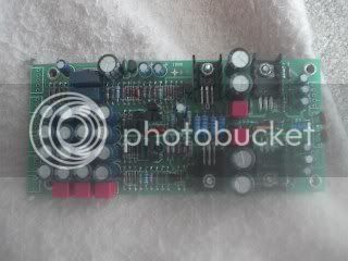
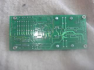
Most of what you need should be in this first post
schematics & tech doc's here
http://www.groupdiy.com/index.php?topic=48791.0
Here is some info from Dan and would like to not bother him
with too many questions , most are answered in thread
F.E.T. resister value need to be determined in circuit , see instructiuons
below , not sure if there is much else tricky ,
Adding some info here so it is easier to find
power xfmr requirements = An off the shelf 30va 22 + 22 transformer will power this up fine
you don't need to build the supply in the schematic , although it is nice with o/l l.e.d. drivers
Good supply design with comparitors for overload [ they work nice ]
though they are they only part that is surface mount size [ on psu pcb ]
Simple " raw dc " psu design cam be used with 22-0-22 30va psu Xfmr
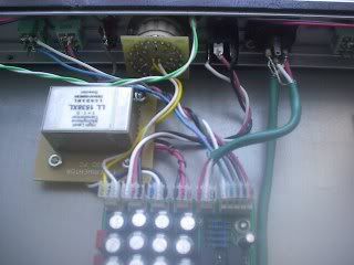
Suggested input Xfmrs
Cinemag CMMI-5C 150:3750
Lundahl 1538 XL 1+1:5
Jensen JT-13K7 1:5
Outputs Cinemag CMOQ-1H
Or Jensen JT-11-BM
Any 24 pos. shorting switch may be used for the gain control , although not recommended a 2k2 reverse log pot may be used to get the pre working until you find a switch
Finding the value for R46 [ with fet ]
R46 is determined by putting a FET in the circuit, then adjusting
for minimum output offset. This value drifts some with temperature, so
I try to adjust for <.5mv when the circuit is warmed up.
You are selecting r46 for minimum output offset voltage at output
[ before output transformer of course , if you installed one ]
just power the board up, it already has the feedback resistor, and put
a 2K or so pot in for R46, adjust for minimum, let things warm up some
more and readjust. After 15 minutes or so take the pot out of the
circuit, measure and replace with a fixed resistor of the closest 1%
value and then retest for warmed up minimum offset.
It takes a little while, but it's something you can walk away from in
between tweaks.
Further refinement [ and quote ] from Dan on slecting the resister
When adjusting for R46, I first power the boards up, and see that the
offset is less than about 15mV, and frankly I forget which polarity.
This proves that the FETs are a reasonable match.
Then insert the trimpot in for R46, adjust for zero offset, which you can't
do because just breathing on the board will move it a little, but you can
get it trimmed into less than 1mV pretty easily.
Remove and measure the trimpots, then replace with the closest 1%
resistor you can get.
It's not super critical, the offset won't get any worse, and anything under
5 or 10mV's of offset isn't going to cause any problems.
Grounding scheme
As recommended by Dan
Run a heavy bus wire along the back of the i/o connectors - in Canada & U.S. the copper house wire fits perfectly into the XLR connector
Have the Chasis & PSU grounds meet at this point
Run the Preamp board ground [ including the psu ] to this point
Run the Input Xfmr screen & ground as well as any shielded i/o wire to this point , preferably between their respective i/o connectors .
Do not connect any of these grounds [ i/o & Xfmrs ] to the input side of the board
regards Greg


![Electronics Soldering Iron Kit, [Upgraded] Soldering Iron 110V 90W LCD Digital Portable Soldering Kit 180-480℃(356-896℉), Welding Tool with ON/OFF Switch, Auto-sleep, Thermostatic Design](https://m.media-amazon.com/images/I/41gRDnlyfJS._SL500_.jpg)


