Green mic pre Buzz and phantom power hum

GroupDIY Audio Forum

Help Support GroupDIY Audio Forum:

This site may earn a commission from merchant affiliate links, including eBay, Amazon, and others.
amaurythewarrior said:
Right now my XLR IN 1 is going to the PCB, do you think I should change that?

PIN 1 of the XLRs and any shield should ONLY connect to Case bolt/chassis


If you have a shielded twisted pair cable going from the input XLR to the PCB, cut the shield connection to the 3 pin molex at the PCB end and put heat shrink around the cable.
Leave the shield only connected at one end, to PIN1 XLR.
Then Pin 1 connects to case/chassis
 
Rob Flinn said:
Looking at the picture of the wiring in your unit, it looks like it could do with tidying up. 

Rob is completely right, your project is really messy.
It looks like a spaghetti incident.

You need to tidy it up

1) Toroid transformers emit more or less EMI depending on rotation, did you rotate the Toroid for the least EMI possible?
2) Cables from the input XLR to PCB and from the PCB to Output XLR should be twisted pair shielded cables
3) twist the + and - and 0v wires from the PSU to the preamp pcb
4) twist AC voltage wires from the IEC to the Toroid core
5) Try to cross voltage wires and audio wires with a 90 degrees angle
6) keep all wires as short as possible
 
I know it's really messy, although I had never heard the phrase "spaghetti incident". ^^
As I said, this was my first project and I made a lot of mistakes, on the case for example, and I wanted to a nice installation in a new case once the problems were fixed, but maybe the installation itself does matter more in the problem than I thought....

I knew some of the things you mentioned but clearly not all that, I'll try, I'll need to get some shielded cable, I don't have any.

Also concerning toroid rotation... Can I know in advance the optimal rotation, or should I just try different orientations?

(a lot of this I've a on a tube amp kit I've done recently, shielded cable with shielded connected to ground on only one side, twisting and crossing cables only at 90° - Somehow I assumed it mattered only for high-gain, but I guess it's silly, noise is noise, you always want to minimize it).

So thank you both, I'll try that and report back.

edit:
Another question that I have is concerning wire and gauge... I have only 0.2mm² in the pre, or close. Does it have any effect for noise or other in a pre. I have used single core for the first time in the guitar amp kit I did, and learned that it was more convenient for wiring in some cases. But the voltages didn't compare, obviously.
 
Guns_n%27_Roses%3B_Spaghetti_Incident%3F_cover.jpg
 
amaurythewarrior said:
Also concerning toroid rotation... Can I know in advance the optimal rotation, or should I just try different orientations?

Listen noise, rotate the toroid while listening, stop the rotation when the noise is the least possible. Mark the Toroid in that point and screw it.

stray_field.gif


_______________________________________________________________

You can also use a trafo shielding sheet, but to be honest I don't think thats your problem

https://www.don-audio.com/trafo-shield
 
I found this picture of the inside of my 4x green.    I didn't use screened cable anywhere and there is no hum.    It looks like I probably connected the PSU 0v to the star chassis ground, & pin 1's to the star ground as well.  The star ground is a M4 nut and bolt screwed through the chassis with a crinkle washer on both sides of the panel to make a good connection.  Each wire attached use a ring terminal & is secured with crinkle washer & M4 nut.  The Ov is taken from the pin 1's on the input sockets to the pcb input connections which is how the pcb's are connected to 0v.  I like this because the 0v doesn't go through the pcb to connect to a mic.  The green wire you can see going round to the front panel from the PSU 0v board is just for the phantom led.


Not the neatest job I've ever done by a long way & if I were to do this again I might use screened cable, but would probably make the 0v/chassis ground connections in the same way,
 

Attachments

  • 20200905_142727_resized.jpg
    20200905_142727_resized.jpg
    997.1 KB · Views: 42
55v is too high for the phantom. Check the resistors around the phantom 317, and make sure they are correct.

How does the mic pre work with a dynamic mic? i.e. not using the phantom?

Here is a doc that can help you check your voltages. I see you have the 4th diode and caps in the Phantom section installed. This can result in high voltages that might blow the LM317.

I also ground everything to the star ground. So I run a wire from pin 1 on each XLR to the star. A wire from each preamp board to the star. A wire from the PSU to the star, and the wall socket earth to the star. I have found this to result in a VERY quiet mic pre.

Hope this helps, and thanks to the others for stepping in.

adEm0Gb.gif
 
Hello peterc, and thank you for the assistance.
I have most of these docs, but not for the specific version I have I think.

I have measured the voltages again, they're actually correct...
Even lower, where it says 63v I have "my" 55v, and then the fourth diode doesn't seem to make a difference. I still measure 55 after it, which is what I get out of the PSU. Should I still get rid of the 4th diode?

I did a "cleaner" setup today (no shielded wire so far), but it didn't change much, and definitely made no difference to the phantom hum. If the voltage out of the PSU is (relatively) correct, and it happens only when the phantom power is switched on, shouldn't it come for the preamp board?

The thing is, I made 2 which both have the same problem...
 
It works fine with a dynamic (other than a little buzz definitely ground related since it was largely reduced by the 0.1Uf and 10R trick).
As soon as I kick in phantom power, very loud hum (affected by the gain)
Same behaviour with condenser mic (and the mic is actually powered and I get sound, but the the hum is excessively loud)


peterc said:
Yes, take out the 4th diode and put in a link.

Does it work OK with a dynamic mic?
 
Thanks Rob, I'm having a closer look at what you've done.

Rob Flinn said:
I found this picture of the inside of my 4x green.    I didn't use screened cable anywhere and there is no hum.    It looks like I probably connected the PSU 0v to the star chassis ground, & pin 1's to the star ground as well.  The star ground is a M4 nut and bolt screwed through the chassis with a crinkle washer on both sides of the panel to make a good connection.  Each wire attached use a ring terminal & is secured with crinkle washer & M4 nut.  The Ov is taken from the pin 1's on the input sockets to the pcb input connections which is how the pcb's are connected to 0v.  I like this because the 0v doesn't go through the pcb to connect to a mic.  The green wire you can see going round to the front panel from the PSU 0v board is just for the phantom led.


Not the neatest job I've ever done by a long way & if I were to do this again I might use screened cable, but would probably make the 0v/chassis ground connections in the same way,
 
Whoops said:
PIN 1 of the XLRs and any shield should ONLY connect to Case bolt/chassis
If you have a shielded twisted pair cable going from the input XLR to the PCB, cut the shield connection to the 3 pin molex at the PCB end and put heat shrink around the cable.
Leave the shield only connected at one end, to PIN1 XLR.
Then Pin 1 connects to case/chassis

A well-known manufacturer does not share the same philosophy in one of its products (3000 € or $).  :)
 

Attachments

  • pin one problem.jpg
    pin one problem.jpg
    329.6 KB · Views: 36
moamps said:
A well-known manufacturer does not share the same philosophy in one of its products (3000 € or $).  :)

As some other manufacturers, and them they make something that is called "The Pin 1 Problem"
This problem has been well discussed.
This is a good reading:


https://www.ranecommercial.com/kb_article.php?article=2127

The "Pin 1" Problem

Many audio manufacturers, consciously or unconsciously, connect balanced shields to audio signal ground; pin 1 for 3-pin (XLR-type) connectors, the sleeve on 1/4" (6.35mm) jacks. Any currents induced into the shield modulate the ground where the shield is terminated. This also modulates the signal referenced to that ground. Normally great pains are taken by circuit designers to ensure "clean and quiet" audio signal grounds. It is surprising that the practice of draining noisy shield currents to audio signal ground is so widespread. Amazingly enough, acceptable performance in some systems is achievable, further providing confidence for the manufacturer to continue this improper practice -- unfortunately for the unwitting user. The hum and buzz problems inherent in balanced systems with signal-grounded shields has given balanced equipment a bad reputation. This has created great confusion and apprehension among users, system designers as well as equipment designers.

Similar to the "pin 2 is hot" issue, manufacturers have created the need for users to solve this design inconsistency. Until manufacturers provide a proper form of interconnection uniformity, users will have to continue their struggle for hum-free systems, incorporating previously unthinkable practices.

The Absolutely Best Right Way to Do It

Clearly, the available literature prescribes balanced interconnection as the absolute best way to interconnect audio equipment. The use of entirely balanced interconnection with both ends of the shield connected to chassis ground at the point of entry provides the best available performance.

The reasons for this are clear and have been well-documented for over 60 years. Using this scheme, with high-quality I/O stages, guarantees hum-free results. This scheme differs from current practices in that most manufacturers connect balanced shields to signal ground, and most users alter their system wiring so only one end of the shield is connected. Due to these varied manufacturer and user design structures, an all-encompassing recommendation with proper coverage of both balanced and unbalanced interconnection is essential.

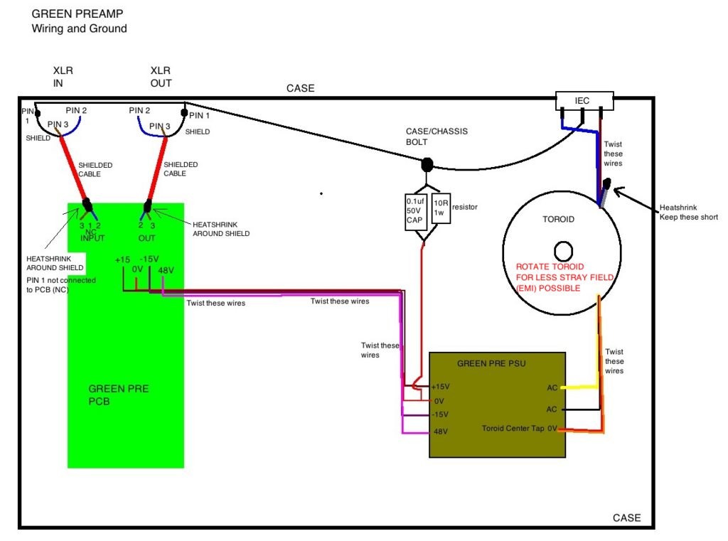
Conceptually, it is easiest to think of shields as an extension of the interconnected units' boxes (see Figure 1). Usually, metallic boxes are used to surround audio electronics. This metal "shell" functions as a shield, keeping electromagnetic fields in and out of the enclosure. For safety reasons, the enclosures in professional installations are required by law to connect to the system's earth ground (which in many systems is not the planet Earth -- an airplane is a good example).

Balanced cable shields should function as an extension of the enclosure.


index.php
 

Attachments

  • Screen Shot 2020-09-06 at 00.56.26.png
    Screen Shot 2020-09-06 at 00.56.26.png
    44.7 KB · Views: 69
amaurythewarrior said:
I did a "cleaner" setup today (no shielded wire so far), but it didn't change much,

Even if the problem is elsewhere in the build, I did a drawing of the wiring layout and a better way to do the ground to help you out.

AZIA5WKh.png

 
Thank you for the detailed drawing, that's pretty much I did based on yesterday's explanation (but I wasn't sure I had understood everything properly). I'm sure it will help more beginners.
I still have to get shielded cable, next time I order some parts.

Whoops said:
Even if the problem is elsewhere in the build, I did a drawing of the wiring layout and a better way to do the ground to help you out.

AZIA5WKh.png
 
And peter, I'll try removing the 4th diode like you said. But if I understood you right, it's just a precaution and has nothing to do with phantom power noise?

Has noone any idea about that specific problem? None of the things I tried have had any effect on this.
 
amaurythewarrior said:
I still have to get shielded cable

It's a balanced connection, a short distance and also the metal case is providing shielding from outside sources so you will not notice a diference probably, but it's better to have shielded than not to have it, you have a shield protecting those cables from inside the case interference.
 
amaurythewarrior said:
Has noone any idea about that specific problem? None of the things I tried have had any effect on this.
First measure DC voltage on phantom +48V output,  if it's more than 48V, do not connect any condenser microphone.
then  measure AC voltage on the same output (set your voltmeter to AC,  2V or 200mV ),
check the DC phantom voltage on XLR, pins  2 and 3 when phantom is on,
check the DC and AC voltage between pins 2 and 3 on input XLR,
report back.
 
Print the PSU schematic, follow it and measure and check each component one by one, highlight on the schematic all the components that measured correctly or are good.
Check all component values, sometimes people swap a 220R resistor for a 220K, or a 10uf cap for a 100uf cap or vice-versa, re-check that. Measure all diodes with the multimeter.

Check the PCB traces for solder joints between adjacent tracks or pads, check for colder joints also

Measure the voltages like Moamps said and also measure all the voltages that are in the layout provided by PeterC,
write your values underneath the written ones and show us all.


Attachments

  • adEm0Gb.png
    adEm0Gb.png
    109.6 KB · Views: 19

Latest posts

Back
Top