Green mic pre Buzz and phantom power hum

GroupDIY Audio Forum

Help Support GroupDIY Audio Forum:

This site may earn a commission from merchant affiliate links, including eBay, Amazon, and others.
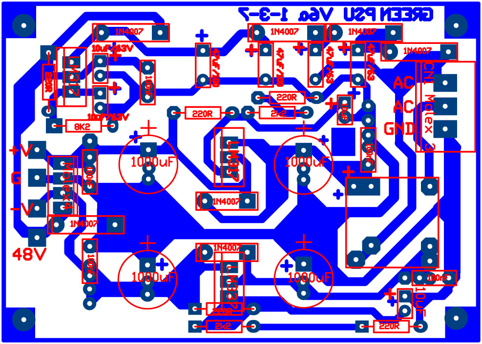
The board you have is different than someone posted earlier. Look closer to the bottom, the wire you soldered connects in and out of the IC. Just cut it and try once again.
 
Apologies again, did not check the version number.

Here is the correct overlay. I changed the design to only have 3 stages in the phantom section, the 4th diode is actually a protection diode for the LM 317.

O55AFOj.jpg


Rob is right in that the TL783 is a better choice, but I have built more than 50 of these PSU PCBs using LM317s with no problem at all.

So Amaury, take out the link and put the diode back in. If you do not have one, it is not serious, it will work without the diode but be careful of shorts. Otherwise it all looks OK on the top side. Check for odd shorts on the under side.

Peter
 
Peter, please don't apologize, I have you to thank for my introduction to the world of DIY studio gear. It is kind enough of you to take time to support your design.

Anyway, after what moamp told me I put the diode back, (after replacing the LM317), and it made a big difference. I think I still have a bit of hum, and noise, but nothing I can complain until it is properly, cleanly wired in a case.

My phantom voltage is now lower, however... Around 43 (still not very accurate on analogue meter).
I imagine it's safe because it's lower and regulated - which I assume means before the voltage was not regulated? (bit scary to think I tried expensive mics on this).
I'm wondering, how do I get to 48? The last diode brings the voltage down before the regulator? (from 55 because I don't reach 63v anywhere)

But thanks again to everyone who helped, this is "sort of" working right now, and I've learned a lot of things I didn't know.
 
Congratulations on the progress and thanks to Peter for the technical support.
The phantom output voltage that is now 43V can be slightly raised by connecting a resistor parallel to the 220ohm resistor. Its value can be 3.3 kohm or 4.7 kohm. If this fails to raise the voltage, then the voltage at the IC input is too low. Can you measure the DC voltages at the cathodes of the diodes?
Also, you can check the presence of hum AC voltage at the + 48V output using some cheap headphones and one electrolytic capacitor with a value of about 1 to 10uF/50 or 63V. Using clips connect + pol of capacitor to + 48V output, - pol to headphones input left or right, ground on headphones to gnd on board. If there is a hum at the + 48V output, it will be heard in the headphones.
 
Rob Flinn said:
Sorry, disagee with you there.  if someone is using the mic pre wired into a patchbay it is quite easy to short the mic pre input if someone plugs in/out of the patchbay while the phantom is on.  In the case you talk about that would put 63v across the 317.
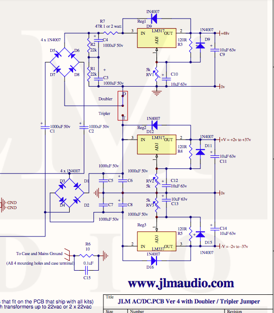
Providing short circuit protection for the LM317 it's really simple and costs 18 cents. 2 Diodes are used. Most PSUs I've used use that protection:

Diode D1 protects from internal short circuits & Diode D2 protects from external short circuits

FWLJCYFJ3KFDQH2.LARGE.jpg


A PSU I use a lot and it's very well designed PSU, the JLM PSU,  has that protection in all the Regulators:

MPCIMFk.png


Saying this, thanks for recommending the TL783 I will definitely trying it in the future.
But using an LM317 with 2 diodes costs 50 cents total and works perfectly and the TL783 costs 1.8€.
So using an LM317 with proper protection it's still a good choice nonetheless.
 
Sorry I don't understand how diode 2 protects against external shorts. 

The way I understood it was that diode one prevents the scenario when the output is at a higher voltage than the input, which  the reg doesn't like & would blow it.    Diode 2 prevents the Adj leg becoming more positive than the output leg which would also blow the reg.   

Maybe I have this wrong, please explain ?
 
Both diodes protect the regulator from caps discharge in the event the input or output gets shorted. The LM317 has built in output short protection on it's own.  The protection might not be as sturdy as the TL783.

but hey let's not hijack this thread


Whoops said:
Both diodes protect the regulator from caps discharge in the event the input or output gets shorted. The LM317 has built in output short protection on it's own.  The protection might not be as sturdy as the TL783.

but hey let's not hijack this thread

I agree with that, but if there is more than 37v across the reg the diodes won't protect it.
 
Better protection is to use a Zener diode of 30v or so in place of the 1N400x I have in there. Check Jakobs G9 schematic for an example.

Amaury, what is the voltage with no mic connected? I f you have a mic connected it will pull the 48v down to a lower value, sometimes as low as 25v, which is the lowest I have seen.
The LM317 formula gives a value of 47.84v using a 220R + 8k2 combination.
 
Whoops said:
Both diodes protect the regulator from caps discharge in the event the input or output gets shorted.
The diodes do not protect IC from too high IN-OUT voltage difference when the output is shorted. Peter suggested a Zener diode across IC to additional protection, it should be rated 3 or 5W.  In this application this IC works fine if the number of channels is small, but I will never try to save 1€ in this position, so I'm with Rob here, TL783 should be used. 
 
I'm assuming that voltage is at the XLR pins 2/3, ie. after the 6.8k resistors. Otherwise, something (else) is seriously wrong ::)

peterc said:
Amaury, what is the voltage with no mic connected? I f you have a mic connected it will pull the 48v down to a lower value, sometimes as low as 25v, which is the lowest I have seen.
The LM317 formula gives a value of 47.84v using a 220R + 8k2 combination.
 
I measure something close to this... (in yellow) That's with no mic connected.
And actually, 35v AC across my input on the board... (from the transformer, I mean)
 

Attachments

  • voltages.jpg
    voltages.jpg
    305.1 KB · Views: 15
From the other thread, the LM317 requires a minimum load of 10mA to regulate correctly.
The voltage setting resistors only draw about 5mA, so unless there is a Phantom On LED drawing another 5mA, the regulator my not be regulating properly
 
So what you're saying is the voltage might not be right if there's no load? But, higher or lower?

Walrus said:
From the other thread, the LM317 requires a minimum load of 10mA to regulate correctly.
The voltage setting resistors only draw about 5mA, so unless there is a Phantom On LED drawing another 5mA, the regulator my not be regulating properly
 
amaurythewarrior said:
I measure something close to this... (in yellow) That's with no mic connected.
And actually, 35v AC across my input on the board... (from the transformer, I mean)

Then you have 35x1.414 =49.49vd.c when you have rectified it.  The LM317 need at least 3v across it to regulate.  i.e you need to feed it with at least 51v (preferably a bit more).    Therefore if that is what the reg is being fed, it's not massively surprising that you don't get 48v out of it.
 
Rob Flinn said:
Then you have 35x1.414 =49.49vd.c when you have rectified it.  The LM317 need at least 3v across it to regulate.  i.e you need to feed it with at least 51v (preferably a bit more).    Therefore if that is what the reg is being fed, it's not massively surprising that you don't get 48v out of it.
Here quadrupler is used to rise/convert  15VAC to about 60VDC.
 
Back
Top