My understanding is that since that board gets very hot, there are cases where the actual board starts to become conducive due to becoming burnt and turning into carbon.
You are using an out of date browser. It may not display this or other websites correctly.
You should upgrade or use an alternative browser.
You should upgrade or use an alternative browser.
GROUP BUY: Universal Audio 176 - a 100% faithful recreation of a legend! CLOSED!
- Thread starter rainton
- Start date
Help Support GroupDIY Audio Forum:
This site may earn a commission from merchant affiliate
links, including eBay, Amazon, and others.
salomonander
Well-known member
- Joined
- Aug 28, 2011
- Messages
- 951
jslstudio said:Received my kit. Looks great came out great.But, The one thing that I think needs to be addressed is the PSU Turret board.
It barely fits the original 10ohm and 30 ohm Koolohm resistors.
And In my opinion to thin.
These Boards get very hot!!! I ave a original....It twice the thickness almost then the kit one. And the turrets should be large
on the PSU board.
The good thing is this board is easy to make. But It is to small and thin. Just a Heads up...It will work.
But should be thicker and more spaced out for the original Koolohms.
Git looks great though!!! Nice work......
John
ps: is this the case for the psu board only? that wouldn't be too bad. devil sits in the detail
DonnieDarko
Well-known member
- Joined
- May 26, 2012
- Messages
- 125
Hey guys,
has someone a more recent BOM than the rev 0.2 that Martin sent me a while ago?
Maybe with some mouser/digikey/farnell/banzai/audiomaintenance/surplussales/hairball links?
Would be appreciated!
Thanks!
has someone a more recent BOM than the rev 0.2 that Martin sent me a while ago?
Maybe with some mouser/digikey/farnell/banzai/audiomaintenance/surplussales/hairball links?
Would be appreciated!
Thanks!
Potato Cakes
Well-known member
I received both of my kits yesterday and I am looking forward to getting stared on these. I have all the parts except for output transformers, a couple of the caps, and ladder attenuators. I bought some Elma switches to build some, but I can't seem to find my notes where I had it all mapped out. Has anyone made their own as opposed to using the old Daven attenuators?
Thanks!
Paul
Thanks!
Paul
Hey Martin,
I received my kit a couple days ago. The build quality looks great, but there's an issue with the faceplate... it looks like the lettering/design was silk screened on the wrong side!
I have attached a picture to show the issue. Please let me know what you think would be the best way to handle this.
For anyone that received a package and put it away for the future, I would encourage you to double check as well.
Attachments
TillM
Well-known member
diylan said:Hey Martin,
I received my kit a couple days ago. The build quality looks great, but there's an issue with the faceplate... it looks like the lettering/design was silk screened on the wrong side!
I have attached a picture to show the issue. Please let me know what you think would be the best way to handle this.
For anyone that received a package and put it away for the future, I would encourage you to double check as well.
What do you mean ?
I don't see any issue. It looks like the original UA176.
If you look at the alignment of the holes in my previous post, that's not poor positioning on my part. Most of holes are off on their alignment by at least a few mm. The holes for the front facing screws are also on the bottom, when they should be on top.
Here's a picture with the faceplate flipped (all holes properly aligned).
Here's a picture with the faceplate flipped (all holes properly aligned).
Attachments
diylan said:Hey Martin,
I received my kit a couple days ago. The build quality looks great, but there's an issue with the faceplate... it looks like the lettering/design was silk screened on the wrong side!
I have attached a picture to show the issue. Please let me know what you think would be the best way to handle this.
For anyone that received a package and put it away for the future, I would encourage you to double check as well.
That was definitely screened with the panel upside down. Hopefully Martin can get a replacement out to you.
TillM
Well-known member
Now I see what you mean 
yes, that looks definitely not right
yes, that looks definitely not right
rainton
Well-known member
Sorry guys,
somehow the notifications don’t work anymore - after Dylan wrote me a PM I came back here to find pages of new posts on the kit...
First of all - Dylan: they printed your faceplate upside down - unbelievable
Even stranger that Don Audio didn’t see it when preparing the kits for shipping.
I’ll make sure you’ll get a proper replacement ASAP!
Thanks for the heads up on the PSU turret boards. Since I didn’t have an original unit here I had to judge from pics. Could you measure the thickness and turret size John?
For what it’s worth my prototype has exactly the same turret board as you all have an it’s been working fine for over a year now. It didn’t bend or get burned or whatever.
I think leaving some space between the large resistors and the board is crucial.
Those of you who are also in the analogvibes FB might have seen the progress I made on the wiring layouts.
At the moment I’m sick and in bed but when I’m up and running (and at the studio) again I’ll upload some pics here too.
rainton
Well-known member
diylan's new faceplate is on its way I heard 
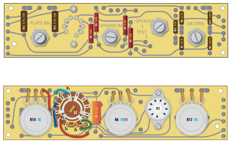
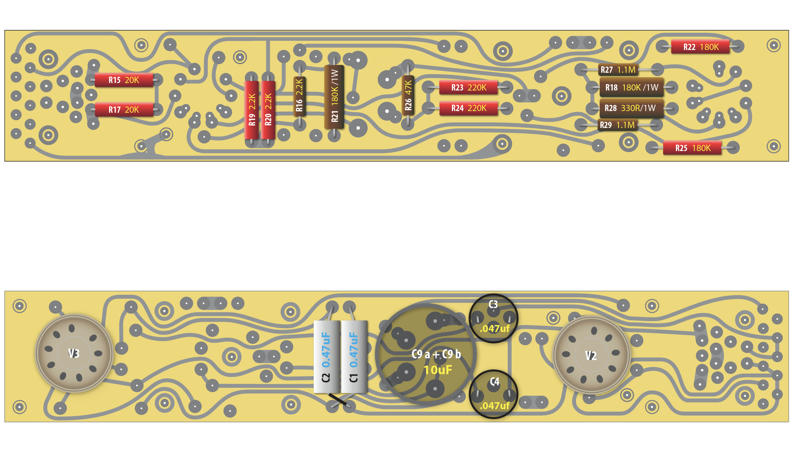
I also attached the first screenshots of the illustrations I made for the wiring layout - here's the upper pcb front & back:

and the lower pcb:

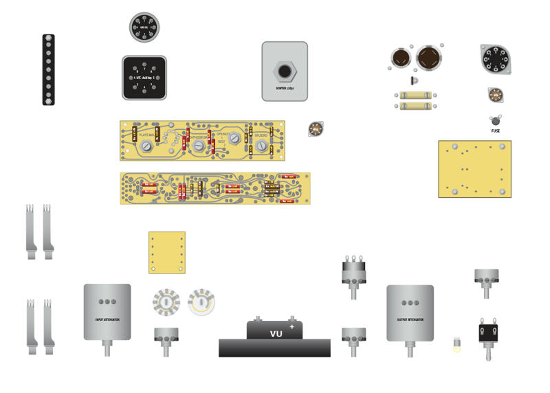
It's all gonna be part of the wiring layout that shows all components - but I'm still working on it - here's another screenshot:

It's a ton of work though.
I'll put together a folder with all the build pics I made while building my prototype and share the link directly with all members of the group buy...
For now here's the corrected schematic (as mentioned before there were quite some errors in there):
http://www.mediafire.com/file/w1wa7eti78ytc3s/Universal_Audio_176_Schematic_CORRECTED.pdf/file
And for those who haven't received it yet the V0.2 version of the BOM. There's no BOM with Mouser links etc. yet, but you're welcome to contribute
http://www.mediafire.com/file/zr69mu542424vfy/analogvibes_176_Parts_List_rev.0_2.pdf/file
Many builders are also over in our analogvibes Facebook group - might be worth checking out for help:
https://www.facebook.com/groups/analogvibes
hope that helps for now
Martin
I also attached the first screenshots of the illustrations I made for the wiring layout - here's the upper pcb front & back:

and the lower pcb:

It's all gonna be part of the wiring layout that shows all components - but I'm still working on it - here's another screenshot:

It's a ton of work though.
I'll put together a folder with all the build pics I made while building my prototype and share the link directly with all members of the group buy...
For now here's the corrected schematic (as mentioned before there were quite some errors in there):
http://www.mediafire.com/file/w1wa7eti78ytc3s/Universal_Audio_176_Schematic_CORRECTED.pdf/file
And for those who haven't received it yet the V0.2 version of the BOM. There's no BOM with Mouser links etc. yet, but you're welcome to contribute
http://www.mediafire.com/file/zr69mu542424vfy/analogvibes_176_Parts_List_rev.0_2.pdf/file
Many builders are also over in our analogvibes Facebook group - might be worth checking out for help:
https://www.facebook.com/groups/analogvibes
hope that helps for now
Martin
Potato Cakes
Well-known member
Hey everyone - I’ve looked thru the thread - so I apologize if this has been covered - but can someone confirm the size of the big and small knobs on the original?
I’m guessing it’s 2 1/8” for the big ones and 7/8” for the small?
Is that correct?
Thanks.
Timothy
I’m guessing it’s 2 1/8” for the big ones and 7/8” for the small?
Is that correct?
Thanks.
Timothy
rainton
Well-known member
mutterd said:Hey everyone - I’ve looked thru the thread - so I apologize if this has been covered - but can someone confirm the size of the big and small knobs on the original?
I’m guessing it’s 2 1/8” for the big ones and 7/8” for the small?
Is that correct?
Thanks.
Timothy
No Timothy, it’s 1,5” for the big ones and 3/4” for the small ones
Martin
salomonander
Well-known member
- Joined
- Aug 28, 2011
- Messages
- 951
do we have any source for the funky capacitors sitting on the back of the unit (the can caps and the two rectangular ones)? cheers
moltenwok
Well-known member
The hayseed 10uf/10uf cap that attaches directly to the pcb will need a tag removed and the others modified to fit the pcb.
DonnieDarko
Well-known member
- Joined
- May 26, 2012
- Messages
- 125
Wow, that are some nice Illustrations @rainton ! Can´t wait to see the completed build instructions!
I accidentally bought 2x C11 from tubesandmore.com - those are the 4x20uF/450V caps. If anyone needs those, I can sell them for what I paid for them.
Located in Germany, already paid tax and customs for them.
Cheers!
I accidentally bought 2x C11 from tubesandmore.com - those are the 4x20uF/450V caps. If anyone needs those, I can sell them for what I paid for them.
Located in Germany, already paid tax and customs for them.
Cheers!
rainton said:diylan's new faceplate is on its way I heard
I also attached the first screenshots of the illustrations I made for the wiring layout - here's the upper pcb front & back:

and the lower pcb:

It's all gonna be part of the wiring layout that shows all components - but I'm still working on it - here's another screenshot:

It's a ton of work though.
I'll put together a folder with all the build pics I made while building my prototype and share the link directly with all members of the group buy...
For now here's the corrected schematic (as mentioned before there were quite some errors in there):
http://www.mediafire.com/file/w1wa7eti78ytc3s/Universal_Audio_176_Schematic_CORRECTED.pdf/file
And for those who haven't received it yet the V0.2 version of the BOM. There's no BOM with Mouser links etc. yet, but you're welcome to contribute
http://www.mediafire.com/file/zr69mu542424vfy/analogvibes_176_Parts_List_rev.0_2.pdf/file
Many builders are also over in our analogvibes Facebook group - might be worth checking out for help:
https://www.facebook.com/groups/analogvibes
hope that helps for now
Martin
Potato Cakes
Well-known member
I'm almost done acquiring all the parts, mostly just down to the output transformers and deciding on what to do about C6 and 7 (rectangle oil capacitors or electrolytics). But I would like if anyone has a link or part numbers for mounts that work with C8, C11, and the UTC-01 transformer.
Thanks!
Paul
Thanks!
Paul
Other pcb boards are good. And mil is good. Just PSU.salomonander said:ps: is this the case for the psu board only? that wouldn't be too bad. devil sits in the detail
But his boards are wider then the original (from left to right ) PSU is small and thinner then original....
Going by eye Martin did an amazing job. But If he does another run. I would like to send him all*** original measurements*** exact!
The 20uf x 4 Hole should also be cut out larger. about the size of the rectifier hole.
The terminal strip used the 4 screws that mount it. Tapped direct in to the chassis. with #4-40 screws.
This kit really could be nailed 100%.....
I will post pics when I get a chance....
Lots of other stuff I am still gathering..Im going for 95% original parts..I also have original UA176 logo meter.
Im also painting my chassis and transformer housing the original GM 1964 light blue metallic.
Similar threads
- Replies
- 122
- Views
- 12K
- Replies
- 4
- Views
- 1K
- Replies
- 27
- Views
- 10K


