GSSL add-on help thread

GroupDIY Audio Forum

Help Support GroupDIY Audio Forum:

This site may earn a commission from merchant affiliate links, including eBay, Amazon, and others.
spreadspell said:
Hi Thanks Harpo!

Yes you have right,
i extended the pins like this way,

https://goo.gl/photos/qDNCewJxkwi5xjbL7
Your pin extension only adresses the different pin spacing.
My remark is for the different pinout. Bottom view in clockwise order -
Multicomp: coil, switch pole1, normaly connected throw1, normaly open throw1 , normaly open throw2, normaly connected throw2, switch pole2, other side of non polarized coil.
Omron: coil, normaly connected throw1, switch pole1, normaly open throw1 , normaly open throw2, switch pole2, normaly connected throw2, other side of non polarized coil.
These are not the only differences, IE Omron current consumption for operating the coil is double of the Multicomp relais.
Already told you, fault fixing is about details.
 
Harpo said:
Your pin extension only adresses the different pin spacing.
My remark is for the different pinout. Bottom view in clockwise order -
Multicomp: coil, switch pole1, normaly connected throw1, normaly open throw1 , normaly open throw2, normaly connected throw2, switch pole2, other side of non polarized coil.
Omron: coil, normaly connected throw1, switch pole1, normaly open throw1 , normaly open throw2, switch pole2, normaly connected throw2, other side of non polarized coil.
These are not the only differences, IE Omron current consumption for operating the coil is double of the Multicomp relais.
Already told you, fault fixing is about details.

Thanks HARPO !
OK Now make sense ...  So, i purchased now the HRS2H-S DC24V from Farnell (9480226).
i hope that the problem was there.

Thank you very much!  ;)
 
DrywOwens said:
Hi everyone!
I have a question regarding a switchable turbo mod on my SSL clone. My "turbo section" is already integrated into my PCB. The trouble is that every time I switch it off (thereby summing L+R into one detector circuit), my gain reduction increases dramatically, making it difficult to make a fair A/B assessment. Of course this is to be expected, as the "turbo off" switch is summing the signals into one detector VCA, so that VCA is getting a hotter signal. I figure I can add some resistors to the "turbo off" switch position to trigger a 3db each, or 6 DB total reduction of the signals being summed to the detector VCA in order to avoid the excessive gain reduction. My question pertains to which value resistor(s) I should be using to attenuate the signals being summed to the detector VCA. Or, what impedance shall I use to calculate the resistor values? Sorry for the basic question and thanks in advance for answering!
Anyone?
 
spreadspell said:
Thanks HARPO !
OK Now make sense ...  So, i purchased now the HRS2H-S DC24V from Farnell (9480226).
i hope that the problem was there.

Thank you very much!  ;)


Hi Again,

So today i received and soldered the HRS2H-S DC24V Relay from Farnell. The only difference is the Make Up Gain. So now when the Compressor button is engaged, the Make Up Gain seems to be working OK. The other pots NO ... (threshod, ratio, attack, release, sidechain 8 way switch.)

i double check with the multimeter for bad solders , and they are ok. i Also check again and again the connections from / to SSC board. I also checked that i use NE5532P instead of NE5532N (bom list) opamps ...
Any Idea, where to start looking at?

Thank you
 
Hi again,

So the SSC worked... ! at last. I had one bad solder somewhere at front Control pcb (pots pcb) and the most important problem was at the molex (6way connector)  !!! very bad quality, and the pins did not stays together... so no connection were made over there. So i remove the molex and the 6 cables soldered to direct to pcb (-15,L,R,0V,-15 ect) so now everything works great ! I have now to adjust the TL, TM with the guide, but i listen some very promissing settings with the SSC...

So Thanks all the friends who helped me here to finish it.
take care  ;)
 
Hi everybody,

is there any active relay bypass pcb available to order?

Have found this one:
https://groupdiy.com/index.php?topic=29770.msg641759#msg641759

And this one (wrong spacing between the jacks for my back panel):
http://diy-tubes.com/index.php?route=product/product&path=59&product_id=283

Thank you
 
just one of the little errors. For the +/-12VDC supplied sidechain part of the circuit you want a current setting 3K9 resistor connecting to this THAT2180 VCAs pin 5, so the turbo silkscreen shows the correct value for Iset  (12V-4*0.7V diode drop)/3900 ohms=2.4mA and the 5K1 at the sidechain VCA on main board (would be only allowing 1.8mA) needs the change to 3K9. (Keep the 5K1 resistors at the +/-15VDC supplied THAT2180 audio VCAs).

I'm coming back on this issue I had with the turbo board and I must say that Harpo was completely right. After doing what he suggested me to do, I don't have this issue anymore... I desoldered the 47k and changed the 5,1k on GSSL's side chain to a 3,9k and made some test after and as I explained in a previous post, the behavior of the unit was really improved but there was still a tiny difference between left and right, but I finally figured out where it came from... And it's not from the turbo side chain, but from the Crush N' Blend that I installed also. When C N' B not engaged, I have a fully balanced stereo signal, but when engaged, right side is about 3 to 6 db louder.

Thanks again Harpo
 
DrywOwens said:
Hi everyone!
I have a question regarding a switchable turbo mod on my SSL clone. My "turbo section" is already integrated into my PCB. The trouble is that every time I switch it off (thereby summing L+R into one detector circuit), my gain reduction increases dramatically, making it difficult to make a fair A/B assessment. Of course this is to be expected, as the "turbo off" switch is summing the signals into one detector VCA, so that VCA is getting a hotter signal. I figure I can add some resistors to the "turbo off" switch position to trigger a 3db each, or 6 DB total reduction of the signals being summed to the detector VCA in order to avoid the excessive gain reduction. My question pertains to which value resistor(s) I should be using to attenuate the signals being summed to the detector VCA. Or, what impedance shall I use to calculate the resistor values? Sorry for the basic question and thanks in advance for answering!


I'm experiencing this too. Is it normal for there to be such a difference between the two states?
 
Hi everyone,

I'm about to install Lundahl output transformers into my GSSL using the Iron output transformer module from Don Audio. The idea is to connect the transformers between the output of the GSSL coming from the board and the output connectors. As the output connectors ground is wired from the input connectors on the GSSL design, do I need to connect the chassis ground to the transformers input ? Maybe stupid question ! :-\

Thanks for your help
 
So I currently have a working GSSL. It's one of the newer boards, I believe. I got it earlier this year. A while ago I purchased Expat's Cavendish mod board because it seemed like a really good upgrade. Assembly of the mod itself is no problem, but I'm having a tough time figuring out how to implement it to my GSSL. It seems like Expat's assembly guide was written with an older version of the GSSL board. The guide mentions removing a 7k5 resistor from the main board, but I can't seem to find it anywhere. They also mention that because of a discrepancy on the GSSL PCB that certain opamp pins had to be switched. I'm wondering if that is still the case with the newer version board.

For reference, I'm using the Cavendish v1.1 board. I'm not sure which version GSSL I have, so I'll just include a picture for reference.

I'd really appreciate any help, I'd like to try and get this mod finished and installed soon.
 

Attachments

  • 2017-08-27 16.26.30 copy.jpg
    2017-08-27 16.26.30 copy.jpg
    1.1 MB
Hi! I have a fully working GSSL with turbo mod. Id like to add a single frequency HPF sidechain. Currently I have the HPF jumped on the board. Can I wire a simple SPDT switch with a wima cap to the HPF on the board (like showed in Gustav´s build manual) or do I need to hook up the turbo board as well? If not, how could I do this with a single wima cap and single mini toggle switch?
 
You need to replace the SPDT by a DPDT switch, and copy the pole going and coming from your GSSL board, to and from the turbo board. If you make some research you should find some post talking about it as I wanted to do the same. I did it and it work like a charm.

 
NEW CAVENDISH GUIDE

Hi everyone! Super excited to announce that my GSSL with Cavendish mod is fully functional and problem free after a few burnt 10R Resistors and some grounding scheme re-work. Since I used both the latest revision GSSL board as well as Cavendish board v1.1, I wanted to share the answers to some of the questions I had while I was putting it together to hopefully save anyone else attempting the modification some time looking for answers.

1. IC Pinout.
You MUST still follow the pin transpositions for the 5532 output chips. For reference, Pin 1 is swapped with Pin 7, Pin 2 with Pin 6, and Pin 3 with Pin 5. This question was answered in the original cavendish thread, but I wanted to post it here as well in an attempt to make the info easier to find.
Another note about the IC Pinout. On the Cavendish Board, the correct pinout is as follows

5--------4
  |            |
6              3
  |            |              Expat Audio Cavendish
7              2
  |            |
8--------1

If you're reading the text on the cavendish board normally, then the pinout is as depicted above.
Posting this in case you're like me (stupid) and soldered the headers onto your board so long ago that you start to second guess yourself.

2. Omitted resistors.
Again, this has been answered previously, but if you're using the new GSSL, the resistors you should remove are 15k, not 7.5k. You can find these resistors easily by looking for your output ICs. The resistors are right along the long side, next to the tan ceramic disk capacitors. Also, when buying the resistors for the cavendish, you should be using a 10k trim and a 10k ohm resistor instead of the two 5ks that are listed in the guide for the older revisions.

3. Grounding and output polarity
In the original GSSL, the ground cable leading from the output section is cut to avoid ground loops. While using the cavendish mod, you have to reconnect that ground (middle pin of the 5-pin output header located on the cavendish board) to the star ground. At first I didn't and it led to very strange results. Also, on my version 1.1 board, the output polarity of the header is as follows:

1| -/+/GRND/+/-|5

I have seen other users post on the forums who claim to have different output orientations, but this is what worked for me with my board. As always, make sure you test for yourself.

Those were my biggest questions going into this build, and what I've posted above are the steps that led me to a fully functioning unit. Hopefully, if you're adding this mod to your GSSL, this will have saved you some time searching through the forums and some frustration of having to redo work and replace resistors.

Now that I have the Cavendish up and running, it's time to invest in the SSC!
 
Hi Everyone,

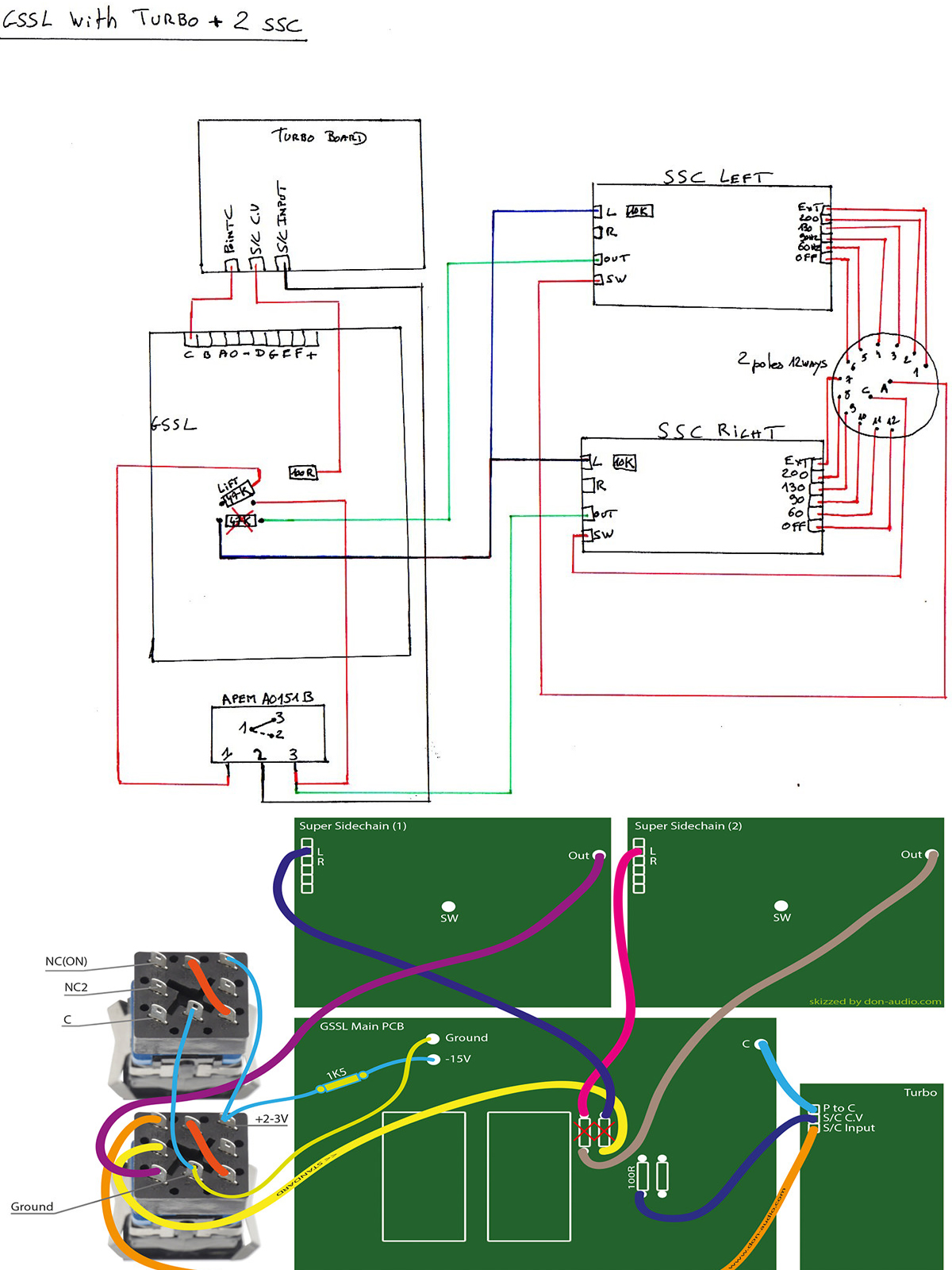
I'm trying to figure out how to properly wire up a few things on my GSSL/Turbo/2 Super Sidechain project.

My question is whether or not I need to connect both Super Sidechain boards "Com/On/Off/Pot A/PotB" connections to the back of the control board or if I can just connect the left SSC board connections and leave the right SSC ("Com/On/Off/Pot A/PotB") disconnected?

Also wondering if I use the "In SW "to" and Ret" and LED connections on just the left side SSC board to connect to my "Compression" on/off front panel illuminated switch or do I take it from the control panel and leave these disconnected?

I know a lot of this has been discussed but I haven't found any definitive way of wiring these connections and I'm a bit confused (clearly:)...

My front panel has 2 illuminated switches. TURBO and COMPRESSOR. Each has a DPDT switch and LED "+ and -". I'm trying to wrap my head around wiring them up with all the boards. Any help would be greatly appreciated.

Thanks!
Matt

I'm basing my wiring on these:
wiring.jpg
 
Hi All,

Just wanted to share a successful project, Here is my dual GSSL which i've built to fit into my 1974 API each with DBX 202c gold bars, Super Sidechain, Turbo, Expat VU driver, and Cavendish. 

Debugging included a few pads on the SSC that hadn't "grabbed" on to the solder.... not a fan of this style of PCB, hopefully this won't cause problems in the future.

power supply is off-board +/-18 from my console power supply

Here is a link to a photo album from the build, the finished in console picture can be found at the end!

https://imgur.com/a/nuiwf

Happy building!

EB
 
I am building a GSSL with Cavendish board and hard bypass with relays. Do I have to load the output transformer when the unit is in bypass, or can I just leave the outputs of the EA2503 floating?
Thanks!
 
Hi! Short question.
Do I need to leave out pin 4 (2180) on my turbo board too?
Have Only mainboard and turbo installed.
Hope this thread isn’t dead, it sent me a warning:)
 

Latest posts

Back
Top