GSSL HELP THREAD!!!

GroupDIY Audio Forum

Help Support GroupDIY Audio Forum:

This site may earn a commission from merchant affiliate links, including eBay, Amazon, and others.
[quote author="ixi"]
Hi, thx for answare vertiges .

compressor not work, it's thesame, when i connect 1+8 pin on stage of That chip.
i check and re-check 10 times :)
I don't any external sidechain board for now :)

Ok, i make foto and post here with voltages :)[/quote]

1+8 ? You mean the pins of your VCAs ? What do you use by the way. THAT ? DBX ?

If you short the pins 1 to 8 of the socket of your VCAs, (with no ics, inside), your inputs go directely to your ouputs unaffected by any compression. It's the good way to know if your 5532s and 5534s are all rights.

eD
 
hi,

i connect pins 1+8 and sound go true.

Here its pictur of my gssl

http://www.enote.si/ixi_ssl_21.JPG (full size) :)

and here its results of measurements:

1) TL074CN
*****************
1/+0,24
2/0,00
3/0,00
4/+12,07
5/0,00
6/0,00
7/0,00
8/0,02
9/0,02
10/
11/-12,32
12/0,00
13/0,00
14/0,36

2) TL072CN
*****************
1/7,83
2/0,00
3/0,00
4/-12,29
5/0,00
6/0,00
7/0,00
8/+12,05


3) NE5534AP
*****************
1/+12,37
2/0,00
3/0,00
4/-15,14
5/-0,60
6/0,00
7/+15,07
8/+12,38


4) NE5534AP
*****************
1/+12,41
2/0,00
3/0,00
4/-15,17
5/-0,60
6/0,00
7/+15,07
8/+12,42


5) NE5534AP
*****************
1/+12,43
2/0,00
3/0,00
4/-15,14
5/-0,61
6/0,00
7/+15,07
8/+12,43


6) NE5534AP
*****************
1/+12,36
2/0,00
3/0,00
4/-15,15
5/-0,61
6/0,00
7/+15,06
8/+12,37


7) NE5532P
*****************
1/0,00
2/0,00
3/0,00
4/-15,15
5/0,00
6/0,00
7/0,00
8/+15,07

8) NE5532P
*****************
1/0,00
2/0,00
3/0,00
4/-15,15
5/0,00
6/0,00
7/0,00
8/+15,07

9) THAT 2180LB
*****************
1/0,00
2/0,00
3/0,00
4/0,00
5/-10,89
6/0,00
7/+15,07
8/0,00


10) THAT 2180LB
*****************
1/0,00
2/0,00
3/0,00
4/0,00
5/-10,86
6/0,00
7/+15,07
8/0,00

11) THAT 2180LB
*****************
1/0,00
2/0,00
3/+5,5
4/0,00
5/-8,66
6/0,00
7/+12,06
8/0,00


thx
 
ixi,

BTW, you deleted the wrong post.
busted.gif

You should edit it and correct the "when i connect 1+7 pin on stage of That chip" to"when i connect 1+8 pin on stage of That chip" :wink:

Your voltages look correct to me.
BUT, something is wrong around the VCAs THAT according the fact you use the 2180LB...

Give me 5 minutes... I'll be right back,

eD))
 
OK, here are the links :

http://diy.fischerworks.com/gssl_vca.shtml
http://homepage.mac.com/marten.thielges/gssl/mygssl.html

The reason why you have make the following changes is explained in the links above. Ah yes, it's not in my picture, but of course you have to replace the 3k9 by a 5k1 on the right channel as well.

ixi_ssl_21eD2.jpg


For the sidechain VCA, I've removed the 10k between VCA PIN 5 and 3
and the 47R between PIN 4 and the ground :

ratio_2180eD.jpg


About the 127k, I used a 100k + 50k trimmer for a fine adjustment of the ratios.

The big ? is because, I've never understood why the 3k9 should stay 3k9 and not 5k1 as stipulated in the THAT dada sheet. Because is connected to the -12 Volts rail ? (instead of -15 for the VCAs) I don't know... anyway, I kept the value of 3k9 and it works great ! :green:

eD))
 
The feedback resistor below your op-amp No.4 (should be 15k) looks different than the 15k between label "Output" and your op-amp No.7 (maybe only optical artifact).
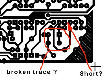
Your different output levels in VCA bypass mode look like missing inverted output on L ch. Look for a broken/lifted pcb trace at the 100uF elco's.
For compression doesn't work, doublecheck part values and orientation on main board and control pcb. Also watch out for shorts and broken/lifted traces on the pcb.
 
[quote author="ixi"] but R ch. it's 2 times louder that L ch. :shock:
Any idea :roll:[/quote]

I haven't seen that part of the sentence... I forgot to scroll to right... :oops:

Harpo, about the feedback resistor... :shock: You have good eyes !! :wink: Yes, it can be a 75k... pretty hard to say actually...

eD))
 
Hi,

I take off here marked elements, i still didn,t replaced 3k9 with 5k1 because i must buy him. (pic 01)
I add at 100k in sidechain section trimer 50k and take off 2 elements 47R & 10K (pic 02).
I must replacet 3k9 just on left ch. or also in right ch. to ??

@Harpo:

i have now inside 27k not 15K ? it's wrong ????

Just for info :razz: .

When i first time made G-ssl went also something wrong, but me master Ales Dravinec from ADRAudio him after completed.
All works, but is's inside all elements. (see picture => www.enote.si/gssl01.jpg)
 
[quote author="ixi"]i have now inside 27K not 15K ? it's wrong ????[/quote]
So your volume difference between L and R is 5,1dB (not 6dB) with a little loss in high frequency.
With feedback resistor 27K and VCA in bypass condition your voltage gain is 1,8 (-AV=27K/15K*). The cap across this 27K (100pF) forms a lowpass filter with -3dB cutoff at 59kHz (=-0,48dB at 20kHz).
Your other ch. has from your pic a 15K feedback resistor, giving voltage gain of 1 = 0dB. The 100pF cap across this 15K forms a lowpass filter with -3dB cutoff at 106kHz (=-0,15dB at 20kHz).
Whatever you decide to change (eigther replace the 100pF across the 27K with a 47pF to get rid of the loss in high frequency or exchange the 27K with 15K), both resistors should have the same value (actually one is 15K and the other 27K). this ones
 
[quote author="vertiges"][quote author="ixi"]
I must replacet 3k9 just on left ch. or also in right ch. to ? [/quote]

Yes.

eD))[/quote]

OK!

[quote author="Harpo"][quote author="ixi"]i have now inside 27K not 15K ? it's wrong ????[/quote]
So your volume difference between L and R is 5,1dB (not 6dB) with a little loss in high frequency.
With feedback resistor 27K and VCA in bypass condition your voltage gain is 1,8 (-AV=27K/15K*). The cap across this 27K (100pF) forms a lowpass filter with -3dB cutoff at 59kHz (=-0,48dB at 20kHz).
Your other ch. has from your pic a 15K feedback resistor, giving voltage gain of 1 = 0dB. The 100pF cap across this 15K forms a lowpass filter with -3dB cutoff at 106kHz (=-0,15dB at 20kHz).
Whatever you decide to change (eigther replace the 100pF across the 27K with a 47pF to get rid of the loss in high frequency or exchange the 27K with 15K), both resistors should have the same value (actually one is 15K and the other 27K). this ones [/quote]

i replace 27k with 15k, but it's the same state :shock:

ssl_overlay_ixi.jpg
 
ixi,

ixi_ssl_z2.jpg


1) Those two resistors designed by the "???" must be 2 120R. They look different, but it could be an optic fx. The ones just under the THAT 9 and 10 look different too. Strange... Maybe caused by the picture... Look at the schematics, the left and the right channel must be indentical ! Check the values of your components.

2) The two others (15k) must be replaced by 2 of 27k for obtaining the unity gain value. It has been discussed here : http://www.groupdiy.com/index.php?topic=1379

3) The two 15k on the left have to remain 15k.

ssl_overlay_ixisd.jpg


4) Don't forget to swap the 3k9 to 5k1 on both channels.

eD))
 
ixi_ssl_z2.jpg


[quote author="vertiges"]1) Those two resistors designed by the "???" must be 2 120R. They look different, but it could be an optic fx. The ones just under the THAT 9 and 10 look different too. Strange... Maybe caused by the picture... Look at the schematics, the left and the right channel must be indentical ! Check the values of your components.[/quote]

Inside it's 120R!
Resistors under THAT 9&10 its the same - it's OK
Left & right channel its identical - identical components and values.

[quote author="vertiges"]2) The two others (15k) must be replaced by 2 of 27k for obtaining the unity gain value. It has been discussed here : http://www.groupdiy.com/index.php?topic=1379[/quote]

i replaced 15k resistor with 27k.

[quote author="vertiges"]3) The two 15k on the left have to remain 15k.[/quote]

OK

ssl_overlay_ixisd.jpg


[quote author="vertiges"]4) Don't forget to swap the 3k9 to 5k1 on both channels.[/quote]

I change 3k9 with 5k1 on both channel.


State it's still the same, righ channel it's lauder then left (sorry Harpo), the same it's when i conect 1&8 pin. And done i put inside That after all no compression :(

I check this what you say Harpo, but it'a OK on left & right NE chip.
I change all NE5532 on output stage and NE5534 on input stage.

Also maybe what kind advise or idea :?: :cry:
 
Jeaa, i found out mistake for what is left ch. quiter, by mistake i ground hot pin on left ch. on stargroun point :roll: "stupid i" :razz:

Problem it in this that still compression doesn't work :evil:

Any advise or idea what's now :?:

Thx
 
ixi,

I'm glad, you finally found what caused the 5.1 dB "offset" between L and R. You see, most of the time the problems come from shorts, bad solders or errors in the component values. Sometimes it's good to take a break and come back later.
For the problem of no compression : there are a lot of cases described and solved in this thread... I know it's long one, but il also the more documented one ! I'm pretty sure all the possibilities of errors/mistakes have been covered...


1) is the orientation of the THAT chip in the sidechain correct ? You can also try to swap it with one of the channel for being sure it works correctely. Pay attention if you put the 2180 in the wrong orientation in the sidechain socket, you'll destroy it. (I know what I'm talking about... :green: )
2) is your bypass is wired correctely ?
3) have you checked all the connections between the main board and the control board ?
4) Check with your multimeter :

TL072 pin1 should change with threshold variations (and with the signal level)
TL072 pin7 should change with makeup variations (and with the signal level)
TL074 pin14 should change with the ratio settings (and with the signal level)

5) Check if you have signal coming at the input of your sidechain: pin 7 of the TL074.
You must have DC varying with signal at the output of the sidechain: pin 8 of the TL074.

eD)))
 
Hi vertiges,

thx for quick answare.

another idea:

it's maybe preble in conection btw main and control board. I have now for conection cabel from computer witch conect Harddisc & mainboard!
It's this cabel OK or NO :oops:

I check this tomorrow evening!

Thx one more time :)
 
Back
Top