GSSL HELP THREAD!!!

GroupDIY Audio Forum

Help Support GroupDIY Audio Forum:

This site may earn a commission from merchant affiliate links, including eBay, Amazon, and others.
Bob1991 said:
I'm building my first clone, and I was wondering if those low-ESR caps in the signal path are really necessary for this application..
Yes

Bob1991 said:
Does it really degrade the soundquality if I use regular 100u and 22u caps?
Yes

Bob1991 said:
Or is it only hearable for 'audiophiles'?
No

Do yourself a favor, don't use crap electrolytic caps in the audio path.....it will sound....well............like crap:)  And it has nothing to do with "audiophile".  Electrolytics are generally not very desirable in the audio path to begin with, so when you do have to use them make sure they're of decent quality.  I doesn't mean you have to spend $20 per cap, but it does mean don't spend a penny on each.

I recommend to use Panasonic FC or FM series.  It will cost around a whopping $5 to do the whole audio section.  If you want to spend about an extra $5, go with Elna Silmec II (digikey).

Bob1991 said:
Another question, I want to make the bypass switch with a regular push-button switch instead of a rotary switch.. I have seen some finished GSSL's with a push button, but haven't found any documentation about. Is it easy to build it with a push-switch?
Push, pull, toggle, rotary - don't make any difference.  All you're doing is completing a circuit when it's switched, the electrons don't care how ya do it:)
 
just edited my question a post ago please its very simple but if someone can give us a hint :) .. are purple and blak ok together or should they go separately? and where? .. (im not sure if that is the only thing my interpretation has wrong)

thanks a lot!
 
ptron said:
2 -what fuse do i need for 115 VAC mains? is  300mA still ok?
This question is transformer dependant. From your following question you have a 15VA toroid transformer. Your Mains voltage isn't a constant and might vary by +/-10%.
15VA / (115V - 10%) mains AC voltage = 0.145A. Round up to the next availiable fuse value 150mA = 0.15A.
Fusing characteristic will be slow blow or T (=time lag) for your toroids higher inrush current.

3- what i understand is.. from my transformer  (digikey TE62053-ND) i connect yellow and red  together and they go to the right leg of the power connector.. black and violet they go together but to the switch "on" leg.(will refer as right leg)
the switch "off side"(left leg) i`d assume it goes to the fuse and from the fuse to the left leg of the power connector (left from inside.)

the center of the power connector would go to the case with a wire onto a screw???

and the center leg of the power switch where do i connect it??

can someone correct me if im wrong? i dont want to blow all my compressor hehe or worse get electrocuted or something!!!

for reference on datasheet it says " For 115 V operation connect primaries in paralell by connecting yellow and red wires together AND BLACK AND VIOLET LEADS WIRES.... ???!!! im not sure the end makes much sense to me ..
Transformer connections look OK. Your mains switch looks like a SPDT switch, so your blue wire, coming from the fuse, would connect to the switch pole, for usual the switches middle pin. Leave your 'off' position unconnected. If this switch is an iluminated switch, connections will be different.
The 'center of the power connector' is safety ground. You want a solid and permanently safe connection here. Scrap off the isolating coating surrounding the screw hole at your 19" enclosure and use a sawtoth washer.
 
harpo man thanks a lot! so i just should change the blue from left to center from the switch then :)

just ...

1 - the blue and green from transformer go in that order onto the pcb? (green left blue right)? does it make a difference?

2- i think my switch is neon lighting inside (u said in a previous post somewhere it might be cus of the contact style) how should i hook it up in that case?

thanks again! im still unable to find isolated jacks for the ssc hehe i think i may have to make yet another order with few bits from mouser haha
!! rookie innit!! ... im just thinking of the few things i already did order and now want/need different one...

2x6  rotary (to stop in 5 steps) i got alpha ones.. (they are pcb mount style so its ok but they are the metal kind)

3 - im not sure i can stop that one to 5 pos. or if i got to get another one made of plastic that will allow me? or can i just make a bridge from the 5th to the 6th position of the switch and just make both positions rel. 2.4mS kinda thing?

4 - CDE caps i got a lot of them!!.. everywhere i turn and read im not sure i like what is being said about these and other caps... im pretty sure i need to get other kind cus i want warmer sound rather than sharp"ish... but would like to know recomendations for these .1uF 63V

5 - isolated jacks ... as i said cant find em downtown mexico city. ;D this ones work?? http://www.neutrik.com/us/en/audio/210_146881/NRJ4HF_detail.aspx or this ones?? http://www.neutrik.com/us/en/audio/210_257211/NMJ4HFD2_detail.aspx

thanks for your help!
 
ptron said:
1 - the blue and green from transformer go in that order onto the pcb? (green left blue right)? does it make a difference?
No difference, besides aesthetical order. Transformer secondary is AC voltage, alternating every 0.02sec for 50Hz mains.

2- i think my switch is neon lighting inside (u said in a previous post somewhere it might be cus of the contact style) how should i hook it up in that case?
Look up the datasheet for your switch, whatever brand/type it is that you have ordered ?

2x6  rotary (to stop in 5 steps) i got alpha ones.. (they are pcb mount style so its ok but they are the metal kind)
3 - im not sure i can stop that one to 5 pos. or if i got to get another one made of plastic that will allow me? or can i just make a bridge from the 5th to the 6th position of the switch and just make both positions rel. 2.4mS kinda thing?
Turn off the fastening nut, take off the washer and pull out the indexing washer. Turn the switch full CCW=counter clockwise. Put the indexing washer back in for position 5. If your rotary switch is different, of course you can link the 5th and 6th throw position for the same timing in these positions. As this is a DIY project, you also could be a little innovative and make a different release timing for this 6th position, just one more cap and resistor or a different series arrangement for another auto timing....

4 - CDE caps i got a lot of them!!.. everywhere i turn and read im not sure i like what is being said about these and other caps... im pretty sure i need to get other kind cus i want warmer sound rather than sharp"ish... but would like to know recomendations for these .1uF 63V
When these drop on a carpet, they will sound warmer than when dropping to a ceramic floor. ::) Comparing same dielectric caps by brand is religious believe IMHO. A different 'sound' of caps with same dielectric is related to caps tolerances that come in range of +/-5%, +/-10% or +/-20%.
 
woo thanks for that harpo i didnt expect such a quick answer !!! i was even editing the previous questions :D hehe !!

5 - isolated jacks ... as i said cant find em downtown mexico city.  this ones work?? http://www.neutrik.com/us/en/audio/210_146881/NRJ4HF_detail.aspx or this ones?? http://www.neutrik.com/us/en/audio/210_257211/NMJ4HFD2_detail.aspx

about the switch.. i got it downtown and i dont have a datasheet.. i dont even know who made it.. mexican manufacturer most likely ...
thats why i ask such silly questions with no info to back it up. sorry :(


btw... about the sixth position for the release i like it!!! maybe something faster than 180k 47u ?

1- if i go half in resistance.. say 90k to be fully half.. would the release be 0.05ms??
or slower than 2.4ms...

2- i got a general question ... the (AUTO) thing on the release what does that stand for or why is it auto?

3- which step would u think is more helpful ? slow or fast? :D

there are a lot of questions there hehe

4 -and if i may ask how would u set it up so its nicely done cus there is no more spaces in the pcb for more caps and res.. should i connect a wire from that leg onto the paralell res/cap and then go into where on the pcb? :)

as always thanks for your help harpo :)
 
ptron said:
5 - isolated jacks ... as i said cant find em downtown mexico city.  this ones work?? http://www.neutrik.com/us/en/audio/210_146881/NRJ4HF_detail.aspx or this ones?? http://www.neutrik.com/us/en/audio/210_257211/NMJ4HFD2_detail.aspx
both would do it. The 1st one requires a separate ordering of the mounting nut.

about the switch.. i got it downtown and i dont have a datasheet.. i dont even know who made it.. mexican manufacturer most likely ...
thats why i ask such silly questions with no info to back it up. sorry :(
...but you have a meter, set for measuring ohms...

btw... about the sixth position for the release i like it!!! maybe something faster than 180k 47u ?
1- if i go half in resistance.. say 90k to be fully half.. would the release be 0.05ms??
or slower than 2.4ms...
there is no 47uF cap in the release section. u47 = 0.47uF or 470nF. Keeping the 0.47uF cap value, a lower value resistor will make the caps discharging time shorter and vice versa.

2- i got a general question ... the (AUTO) thing on the release what does that stand for or why is it auto?
Sure you've read http://www.gyraf.dk/gy_pd/ssl/ssl.htm ?

3- which step would u think is more helpful ? slow or fast? :D
Question of taste. Heavy/distorting effect compression is the cheapest (no cap, no other resistor than the already present/parallel 3M3).

4 -and if i may ask how would u set it up so its nicely done cus there is no more spaces in the pcb for more caps and res.. should i connect a wire from that leg onto the paralell res/cap and then go into where on the pcb? :)
Lots of space on the back side of the pcb  ;)
 
thanks man!!  to answer hehe i hadnt actually read that part of the anatomy fully... or couldnt really understand the timeconstant bits a few months back to be honest ;D it looks great! so i could make another kinda auto bit for the next one too!! im not sure how to measure the times .. which one would be the formula for time like this? i can see .47u (i stand corrected) / 180k would be .1ms and could probably get the idea from the rest of .47u`s but the time constant bit..

... im trying to figure this out.. i can see for sure how resistance is directly proportional to the time but in capacitance... how does the 91k / 6u8 work? what time would that work out to be??

1- i guess my question is .. how would the formula look like for the "time = RES / CAP"? for the 750 /.47 i think id go to 1m2 to make that next timeconstant just that bit longer.. but again.. i would love to see some kind of formula for this two working together to calculate the time to write down on the pannel :D


2- ok i measured my switch ( i tried) with ohmmeter..

now that i look closely one sides wiper is  gold colour and the other 2 wipers are silver..
measuring from the center wiper to the other silver one it varies from 30 to 100 ohm when its on to "no contact" when i switch it off.. but the gold wiper never seems to conduct... (it says 1 on the left of the ohmmeter.. or no reading kinda behaviour) measuring gold wiper vs any of the 2 silver wipers is this normal behaviour?

tomorow im going to the workshop to make holes in the pannels and backplates hehe!! will upload pics now that i got a bucket acct :)

3- ALSO!! about the  caps... i bought lot of this for the 2 builds.. http://mx.mouser.com/Search/ProductDetail.aspx?R=168104J63A-Fvirtualkey53900000virtualkey539-168104J63A-F
polyester ones... i heard to use polypropylene?? i dont understand really the difference are they both the same dielectric=????

4- cus of the colour and not certainty of the power switches i am thinking of swaping for these ones.. would those work for all intents and purpouses?
http://www.mouser.com/catalog/specsheets/MS-100886.pdf

thanks man!
 
ptron said:
1- i guess my question is .. how would the formula look like for the "time = RES / CAP"? for the 750 /.47 i think id go to 1m2 to make that next timeconstant just that bit longer.. but again.. i would love to see some kind of formula for this two working together to calculate the time to write down on the pannel :D
Time for attack and for release is R*C for unlimited current feed, constant level above threshold and a non-feedback design. None of these assumtions are true in this circuit. Use your ears and using a labeling to match your mood/taste might be more precise than any numbers.

2- ok i measured my switch ( i tried) with ohmmeter..

now that i look closely one sides wiper is  gold colour and the other 2 wipers are silver..
measuring from the center wiper to the other silver one it varies from 30 to 100 ohm when its on to "no contact" when i switch it off.. but the gold wiper never seems to conduct... (it says 1 on the left of the ohmmeter.. or no reading kinda behaviour) measuring gold wiper vs any of the 2 silver wipers is this normal behaviour?
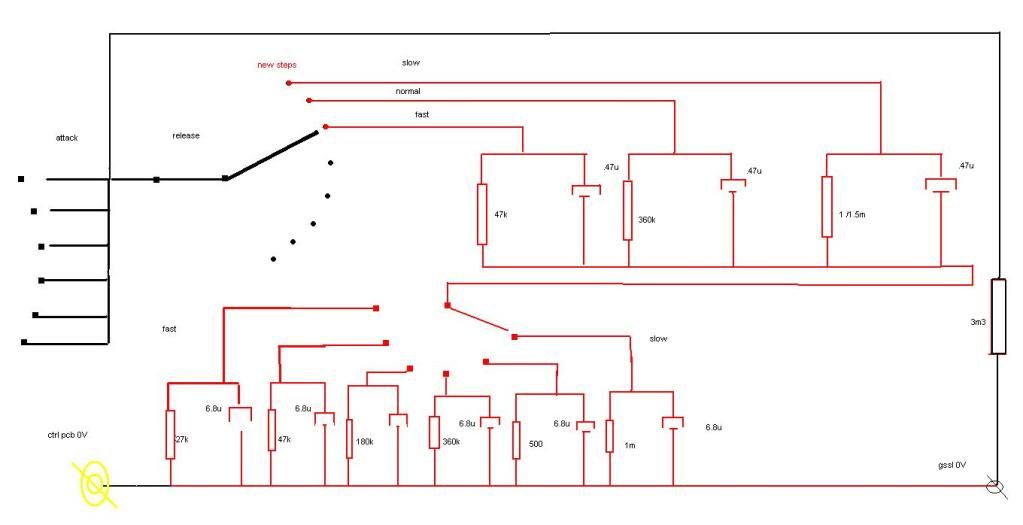
Looks normal for this kind of switch. Hookup might be done like this little drawing

4- cus of the colour and not certainty of the power switches i am thinking of swaping for these ones.. would those work for all intents and purpouses?
http://www.mouser.com/catalog/specsheets/MS-100886.pdf
Obviously not for 'all intents and purpouses'. The linked pdf shows at least 3 different SPxT switches (off-on, on-on, on-off-on). A bypass switch without using a relais would require a DPDT switch.
 
Harpo said:
4- cus of the colour and not certainty of the power switches i am thinking of swaping for these ones.. would those work for all intents and purpouses?
http://www.mouser.com/catalog/specsheets/MS-100886.pdf
Obviously not for 'all intents and purpouses'. The linked pdf shows at least 3 different SPxT switches (off-on, on-on, on-off-on). A bypass switch without using a relais would require a DPDT switch.

no sorry i meant for power switch.. i was looking at the spst i think.. (on off)
 
sorry im still a bit confused with switch terminology... the momentary is the one i have to keep my finger on it yeah? how does that one show on mouser? like "on - (on)" yeah?

would on / off be normal toggle one ? ;D  im guessing this one is about the same ??? i just like more the shape  :D
http://mx.mouser.com/Search/ProductDetail.aspx?R=1055-TA2120-EVXvirtualkey12040000virtualkey1055-TA2120-EVX


ok im thinking of the filter now.. i was thinking to keep the caps values like the 5th release (6.8 and .47u) and wobble a bit with resistor values on a breadboard with croc clips goin to the pcb ... would this method be the one u recommend?

cheers man i hope i dont piss u off with so many dumb questions!!! :p i seen some people getting upset with guys like me that dont know anything but want to get on with it

big thanks harpo  8)
 
ptron said:
sorry im still a bit confused with switch terminology... the momentary is the one i have to keep my finger on it yeah? how does that one show on mouser? like "on - (on)" yeah?
mom, (on) or momentary.

ok im thinking of the filter now.. i was thinking to keep the caps values like the 5th release (6.8 and .47u) and wobble a bit with resistor values on a breadboard with croc clips goin to the pcb ... would this method be the one u recommend?
yes. changing caps values will also affect attack time.
 
safe! thanks for clearin that up hehe

i hope my pcbs get here soon been a good long wait for them (almost 50 days) i went to post office today to ask they said cus of recent terrorist attack lot of post from europe is delayed ... :(

cheers!
 
ok now im thinking a bit more of this release stage ... does it have to come from the filter to the D point on the pcb? and therfore connect to leg 10 of tl074 ?

EDIT:
sorry i realize now (i think) that it has to go on 0v in the control board or in the pin for 0V from control onto the GSSL pcb ? just before the 3m3 ohm resistor..

would someone please tell me if im being a turkey with this assumption?? :D cheers!!

:)

btw.. im working on a time constant circuit sort of thing.. to switch that 6th position on the release onto a second switch to have 3 more options for time constants...

im looking for "SP3T (on - on - on) toggle" cus i dont have much space in my pannel but i only find 8 dollar switches which is a bit extreme for a normal and ugly toggle :D
i found this ones but they need screws and im not into that really :/..
http://mx.mouser.com/Search/ProductDetail.aspx?R=10TS003virtualkey12040000virtualkey10TS003 DP3T on - on - on

i want this kind http://mx.mouser.com/Search/ProductDetail.aspx?R=M2024ES1W01-ROvirtualkey63300000virtualkey633-M202402-RO cus they are screwless ones... but cant seem to find one with decent price with 3 "on" circuits :( will keep looking

can i substitute with something else? i got a couple of rotarys but i dont know about the pannel :D i want a nice design .. but i dont like to pay 20 dollars for damn switches like this its a blag :(
 
ptron said:
btw.. im working on a time constant circuit sort of thing.. to switch that 6th position on the release onto a second switch to have 3 more options for time constants...
??? just use a 1x12 lorlin instead of a 2x6 lorlin. end-stop washer limited to pos.8. done. zero bucks less/more. ;)
 
ok! sounds simple enough :D i didnt think of that tbh ;D ...
:) thanks a lot!!

actually looking into it right now... found the rotary sp8t :) pretty cheap alpha ones !! altho i like the idea of a heavy front pannel with lots of switches and stuff i think you are right less is more..  8)
 
ooookkk !! well.. i thought of some more dynamic way of interacting with the time constant thingy in case some other values / mix of them can work on specific sounds... call it variable time constant i guess..

this would be my sketch

1 -would this work or would i need a 3pole switch instead of the sp6t?? (resistor values are really only for making it slower to faster but they could be different of course)  

2 - would the control pcb 0V (yellow one) be necesary? or just the GSSL 0V?

thanks a lot!!

releasetimeconstantswitchsketch2.jpg


ptron said:
ooookkk !! well.. i thought of some more dynamic way of interacting with the time constant thingy in case some other values / mix of them can work on specific sounds... call it variable time constant i guess..

this would be my sketch

1 -would this work ...
yes, but I'm pretty sure you won't like it, especially the 1300ms attack time.

2 - would the control pcb 0V (yellow one) be necesary? or just the GSSL 0V?
its the same 0V, no matter what colour you've drawn it.

For variable timing this would be my sketch.
 
1 -hrmm.. which one would be the 1300 ms attack? 1m * .47u?..

2- how did you calculate the attack for each stage? id like to do that to be more precise!! :)

tbh i wanted actually one with attack VERY sharp (around 0.05ms one with mild attack (around from .2 - 1ms) and a long one (around 60 - 150 ms (to have a longer attack time for kick drums etc...)


release i was aiming to have something from .05 up to around 10 or 20 ms in the slower stages..

i thought if i didnt move the caps values the attack would remain the same :/ .. i was thinking of this sketch cus i got few switches spare and would like to use them at some point but as i said the resistor values could (should) be changed . thanks for the observation!!

..3- i know its the same 0v but what i mean is.. would i have to connect ctrl pcb into this lil sketch and then from this lil sketch into the 0V from GSSL pcb??

OR
just go normally from control pcb 0V to GSSL pcb 0V and this lil contraption just hook it up in GSSL 0V too??

that was my doubt :)

btw in your sketch...

4- the variable ones are rheostats ??
5 -and the 820R would that be the one on the attack switch pos1?
6- the (auto) that you written there, does that mean the 6.8u loop is the second release time? (kinda the slower one of the 2)???

i know im very lost but would like to figure this out fully and understand how its done so im not like just a building monkey and i understand my machine a bit better

thanks a lot !!!
 

Latest posts

Back
Top