GSSL HELP THREAD!!!

GroupDIY Audio Forum

Help Support GroupDIY Audio Forum:

This site may earn a commission from merchant affiliate links, including eBay, Amazon, and others.
Power works the other way around. You can't give too much power, the circuit draws from the PSU as many "amperes" as it needs. Whether the PSU can handle this or not is another story.
 
Alessio said:
...When I insert the VCA I can't see anymore signal on pin 1...
Your scope is sensing signal voltages. Reread my last post, especially the word 'current'.
Your square waves are from the applied DC from ratio setting with rectified audio at double frequency riding on top.
Nothing to do with your higher VA rated transformer.
Didn't you boost the makeup summing stage by ~10dB from a previous post.
Check, if the 22uF/35V cap between TL074-pin7 and both 20k input resistors from following rectifier isn't broken/leaky.
 
I've tried to change the 22uF caps close to the TL074 but nothing changes... I still have a square wave on pin 1 and 14 of TL074... Pin 7 is a clean sinewave...
I'm stuck again... the voltage rails are fine.
Could be resistors or diodes around the TL074?

Oh and another thing why I don't have any signal on TL072 or on the 5534 in front of the VCA?


Thank tou,
Alessio
 
Hey Harpo I was thinking is somehow possible that the distortion is caused by the fact that I use the SSC boards to bypass the compression like this draw you sent me?

It seems like I'm overloading some opamp... and this causes the distortion. Maybe the square waves that I see on the TL074 are supposed to be like that and the problem is somewhere else...

I'm gonna compare this units with the working one without the SSC and see the differences...
You have any idea???


Thanks,
Alessio
 

Attachments

  • Barclaycon_SSC_dual.gif
    Barclaycon_SSC_dual.gif
    78.8 KB
I think I'm chasing ghosts.
I've used the same settings (fast attack, max compression and max ratio) on an SSL X-logic with the same song and is distorting too!!!
So I've jumped at the conclusion that is SSL design, you can overload the compressor if you want! If I change the fast attack to medium or slow the distortion disappear on both units! (X-logic and mine)

Thanks everyone for your help!
Alessio
 
i got a lil question for whoever might have an answer.... i picked the .1uF caps (25 of em) thinking they were vishay.. turns out they are CDE... is that going to make a huge diference in the sound of my comp? shoudl i go and order vishay or something else? what is the recommended one to use here??

this is the one on the bom
25pcs Polyester capacitors - 100nF/63V 5mm pin spacing

CDE i picked up are 5% tolerance

thanks in advance!
 
I built 2 of these. The only difference between them were the type of .1 caps. And they both sounded different. But they both sounded really good. One was more aggressive sounding and one a bit warmer. But not in a dramatic way. I know what the caps look like but forget the exact types.

EDIT: I used Mouser number 80-CK06BX104K in the more aggressive one. It just had a more edgier sound if that is a word but sounded great. They are boxed ceramics. The other one I used what's in this pic. Forgot my digikey password... http://www.stagefrightrecords.com/gsslback.JPG
Think these are the ones from the BOM on here. They sound warmer. But really it should sound great with whatever. Will just be a bit different.


John
 
thanks a lot john you encourage me to try these ones :D... im tempted to get 25 more of other kind and try that with the second clone :p

will post my progress soon!  ;D

EDIT: btw nice work on your one!! i got a question how did u set the external input if u dont have the ssc board there?  :)
 
yar :)  http://mx.mouser.com/Search/ProductDetail.aspx?R=168104J63A-Fvirtualkey53900000virtualkey539-168104J63A-F

those ones

 
Hello, just a little question: I just received the PCBs and I see a difference between the number of 10Ks and 470Rs on the components list and the schematic.
--> For the NE5532 (output), there is a 470R on the PIN3 and 10K on the PIN5. Is it a mistake on the schematic ?

I have 2 470R at this emplacement on my PCB.

What to do ? ^^
Kevin.
 
sdR said:
..there is a 470R on the PIN3 and 10K on the PIN5. Is it a mistake on the schematic ?..
Yes. There are other differences as well. Pcb silkscreen is the latest version. (I'd use zero ohms instead, YMMV).
 
Okay, this is DIY not paint by numbers.

If you can't find the part number do a search for something similar.

You've got all the info between the schematic, pcb and BOM to find a comparable part.

For example .1uf FILM capacitor turns up 72 pages worth!

Here's one that will work.

http://search.digikey.com/scripts/DkSearch/dksus.dll?Detail&name=P4525-ND

Btw: If you're looking for a less aggressive sound, you only need film for signal bypass caps; not for power supply bypass, those should be ceramic.

In fact you could simply not stuff those poly's and call it a day.

Mark
 
Hi. This is mayby a silly question. I don't seem to have the same gain out from the compressor. If I feed it with a stereo signal the left side are higher in volume out. Even if the signal in is exact the same volume.
And I dont have any place to adjust anything. Hard to explain. Works as expekted otherwise.
Att a picture of the mainbord. Any advsise.

Thanx Mats


Attachments

  • DSCF1405.JPG
    DSCF1405.JPG
    99.5 KB
PAGEN said:
Hi. This is mayby a silly question. I don't seem to have the same gain out from the compressor. If I feed it with a stereo signal the left side are higher in volume out. Even if the signal in is exact the same volume.
And I dont have any place to adjust anything. Hard to explain. Works as expekted otherwise.
Att a picture of the mainbord. Any advsise.
How much difference and is this difference frequency dependant?
If only a fraction of a dB, you might tweak a single resistor (maybe the 27k in front of the audio-VCA or the feedback resistor in the VCA following NE5532 between pins6/7) to catch this imbalance.
Else feed both sides with same low (<500Hz) frequency signal, switch the GSSL to bypass mode and compare each stage L/R, beginning at NE5534 pin6, NE5532 pin7, NE5532 pin1 and correct the wrong resistor value that causes this mismatch.
You might substitute a resistor with a trimmer to dial in the required value, but watch trimmers initial setting.
If imbalance increases when compressing, double check resistor values at the voltage divider 1k/120R, connecting to NE5534 pin3 of the DBX202 substitution circuit.
If the mismatch is frequency dependant, double check cap values.
 
Thanx Harpo.

Did some testing and found a loose wire from the inputjack to the mainboard. Simple and easy fix. I've tested it for 15 min without any problem at all. Then suddenly the left channel fall down 10db. All the time testing with a 100hz tone from the mixer. Same problem if it was bypassed or not. Fiddling around with my fingers on some kontakts and the fault was gone.  :)

Thanx for help anyway. Would have done the test you recomended if I haven't found it that quick.

Now I will start on a 9k preamp. Lots of fun.

Mats
 
I'm building my first clone, and I was wondering if those low-ESR caps in the signal path are really necessary for this application.. Does it really degrade the soundquality if I use regular 100u and 22u caps? Or is it only hearable for 'audiophiles'? Most semi-professional audiogear haven't got them too as far as I know..

Another question, I want to make the bypass switch with a regular push-button switch instead of a rotary switch.. I have seen some finished GSSL's with a push button, but haven't found any documentation about. Is it easy to build it with a push-switch?
 
i got a quick question and it will follow with a big one ....  im not sure im understanding how to connect everything from the mains and all..

1 - ruckus: do you think CDE caps are going to ruin my builds? they are the whole lot of 25x .1uF.. u recommend me asking for a batch of Elna? (btw can i get those on mouser or only digikey?)
ruckus328 said:
Do yourself a favor, don't use crap electrolytic caps in the audio path.....it will sound....well............like crap:)  And it has nothing to do with "audiophile".  Electrolytics are generally not very desirable in the audio path to begin with, so when you do have to use them make sure they're of decent quality.  I doesn't mean you have to spend $20 per cap, but it does mean don't spend a penny on each.

I recommend to use Panasonic FC or FM series.  It will cost around a whopping $5 to do the whole audio section.  If you want to spend about an extra $5, go with Elna Silmec II (digikey).
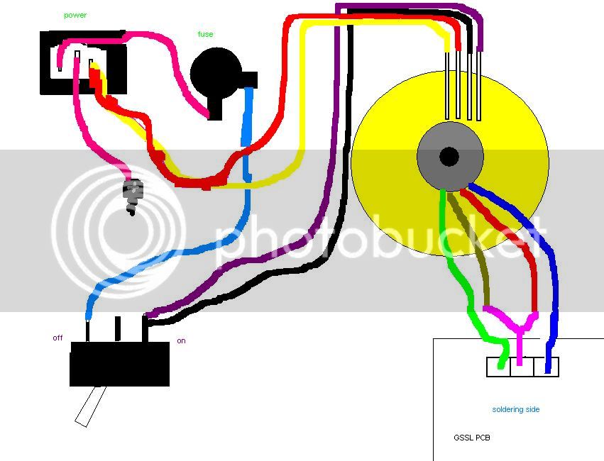

2 -what fuse do i need for 115 VAC mains? is  300mA still ok?

3- what i understand is.. from my transformer  (digikey TE62053-ND) i connect yellow and red  together and they go to the right leg of the power connector.. black and violet they go together but to the switch "on" leg.(will refer as right leg)
the switch "off side"(left leg) i`d assume it goes to the fuse and from the fuse to the left leg of the power connector (left from inside.)

the center of the power connector would go to the case with a wire onto a screw???

and the center leg of the power switch where do i connect it??

can someone correct me if im wrong? i dont want to blow all my compressor hehe or worse get electrocuted or something!!!

for reference on datasheet it says " For 115 V operation connect primaries in paralell by connecting yellow and red wires together AND BLACK AND VIOLET LEADS WIRES.... ???!!! im not sure the end makes much sense to me ..

thanks a lot!! :)

POWERHOOKUPSKETCH.jpg
 
Back
Top