GSSL HELP THREAD!!!

GroupDIY Audio Forum

Help Support GroupDIY Audio Forum:

This site may earn a commission from merchant affiliate links, including eBay, Amazon, and others.
Ngr said:
changing treshold pot seems to make the compressor work ok, let's see how long it will last.
Thanks for your help!
Cool. I think it is probably wise to buy a replacement potentiometer now, as the one you moved looks intermittent, and more than likely it won't get better on its own.
 
Hi Guys,

Just finished my first Gssl and having an issue with not much compression going on?
It all seems to work, haven't checked any voltages yet but seems to pass signal and compress a little when threshold full counter clockwise, ratio on 2, attack release on Full, if i switch ratio to 10 not more compression?
i've used a 4 pole 3 way rotary switch but it maybe possible i have put it in slight wrong?
i did have the THAT2181C in the wrong way round first of all but changed it, could i have damaged it?

let me know if you have any ideas to put this right.

regards

Spence.
 
hi all,

yes it was the ratio pot that was wrong, had to carefully take it out and replace, works fine now, my first one, little bit noisey on the power stage, have ordered the expat ripple board, should sort that out.

Built my second one now and im only getting one channel, the right hand channel working?
have written down all voltages and on the VCA's getting different readings:

Right VCA - 5534 pin 1= 12.23v, pin 2=14.74v, pin 3=0v, pin 4=0.618, pin 5= 12.23v, pin 6=0v, pin 7=0v, pin 8=14.94v

Left VCA = 5534 pin 1= 14.61v, pin 2=14.73v, pin 3=3.048v, pin 4=3.73v, pin 5= 14.56v, pin 6=0.975v, pin 7=0.291v, pin 8=3.73v

TL072 = pin 1=12.05v pin 2 3 4=0v pin 5=3.033v pin 6 7=0v pin 8=11.99v

both input and output IC's seem to have the same values

input 5534 = pin 1= 12.34v, pin 2 3=0v, pin 4=0.618, pin 5=12.29v, pin 6 7=0v pin 8=14.93v
output 5532 = pin 1= 14.73v, pin 2 3 4 5 6 7=0v pin 8=14.93v

may not have written the pin config correctly but i have gone for top left as pin 1 the bottom left as pin 5

the TL074 gets 12v on pins 4 and 12, with pin 1=0.183 and pin 9=0.131v all the others have 0v

any help fault finding on this one would be really appreciated.

i dont have the meter connected as it has not arrived yet but didnt think that this was crucial to getting correct working voltages

regards

Spence.

 
one other slightly worrying thing is when i turn the unit on it doesnt light up the LED, if i then turn it off the led flashes once the unit it turned off, if i then turn it back on it comes on fine?

work that one out?

regards

Spence.
 
Spencerleehorton said:
hi all,

yes it was the ratio pot that was wrong, had to carefully take it out and replace, works fine now, my first one, little bit noisey on the power stage, have ordered the expat ripple board, should sort that out.

Built my second one now and im only getting one channel, the right hand channel working?
have written down all voltages and on the VCA's getting different readings:

Right VCA - 5534 pin 1= 12.23v, pin 2=14.74v, pin 3=0v, pin 4=0.618, pin 5= 12.23v, pin 6=0v, pin 7=0v, pin 8=14.94v

Left VCA = 5534 pin 1= 14.61v, pin 2=14.73v, pin 3=3.048v, pin 4=3.73v, pin 5= 14.56v, pin 6=0.975v, pin 7=0.291v, pin 8=3.73v

TL072 = pin 1=12.05v pin 2 3 4=0v pin 5=3.033v pin 6 7=0v pin 8=11.99v

both input and output IC's seem to have the same values

input 5534 = pin 1= 12.34v, pin 2 3=0v, pin 4=0.618, pin 5=12.29v, pin 6 7=0v pin 8=14.93v
output 5532 = pin 1= 14.73v, pin 2 3 4 5 6 7=0v pin 8=14.93v

may not have written the pin config correctly but i have gone for top left as pin 1 the bottom left as pin 5

the TL074 gets 12v on pins 4 and 12, with pin 1=0.183 and pin 9=0.131v all the others have 0v

any help fault finding on this one would be really appreciated.

i dont have the meter connected as it has not arrived yet but didnt think that this was crucial to getting correct working voltages

regards

Spence.
Check your -15V power supply.  Looks like your input and output op amps are saturated and clamped at VCC.

Pin 4 of the 5534 should be -15V.

And make sure you've got your pin numbering straight, otherwise no-one will be able to help you.
Viewed from component side....
Pin_numbering_01_Pengo.svg
 
Hi Metoo2,

thanks for the heads up on that, noob to IC's so need to get this pin config correct, sorry.
This other unit is using THAT2180 rather than THAT2181 in the other working one.
Also my IC's have dot, which i assume is by pin 1?

regards

Spence.
 
this is the voltages on my working version with hopefully the correct pins mentioned!!!

VCA Left
pin 1= 12.06v
pin 2 = 0v
pin 3 = 0v
pin 4 = 15.32v
pin 5 = 0.608v
pin 6 = 0v
pin 7 = 14.92v
pin 8 = 12.05v

very simliar voltages on the right VCA i think the only one that is different is pin 8 that is 12.08v

on the non working unit these are the voltages again hopefully with the correct pin config:

VCA Left
pin 1= 0.674v
pin 2 = 0.304v
pin 3 = 0.520v
pin 4 = 0.239v
pin 5 = 0.662v
pin 6 = 0.304v
pin 7 = 0.726v
pin 8 = 0.677v

this is when it is turned on and led doesnt come on? i check the voltage to the led when this happens and its only getting 1.4v?
when i turn off and then on again it gets 2.888v and LED works and now the VCA gets more voltage?

VCA Left
pin 1= 14.61v
pin 2 = 0.995v
pin 3 = 0.295v
pin 4 = 0.893v
pin 5 = 3.82v
pin 6 = 3.107v
pin 7 = 14.77v
pin 8 = 14.67v

very strange indeed?

all help very welcome. :)

regards

Spence.
 
Spencerleehorton said:
this is the voltages on my working version with hopefully the correct pins mentioned!!!

VCA Left
pin 1= 12.06v
pin 2 = 0v
pin 3 = 0v
pin 4 = 15.32v
pin 5 = 0.608v
pin 6 = 0v
pin 7 = 14.92v
pin 8 = 12.05v

very simliar voltages on the right VCA i think the only one that is different is pin 8 that is 12.08v

on the non working unit these are the voltages again hopefully with the correct pin config:

VCA Left
pin 1= 0.674v
pin 2 = 0.304v
pin 3 = 0.520v
pin 4 = 0.239v
pin 5 = 0.662v
pin 6 = 0.304v
pin 7 = 0.726v
pin 8 = 0.677v

this is when it is turned on and led doesnt come on? i check the voltage to the led when this happens and its only getting 1.4v?
when i turn off and then on again it gets 2.888v and LED works and now the VCA gets more voltage?

VCA Left
pin 1= 14.61v
pin 2 = 0.995v
pin 3 = 0.295v
pin 4 = 0.893v
pin 5 = 3.82v
pin 6 = 3.107v
pin 7 = 14.77v
pin 8 = 14.67v

very strange indeed?

all help very welcome. :)

regards

Spence.
Yes, on a 2181 the pin marked with a dot is pin 1.

The VCA is a current controlled device. You won't get a whole lot of sense measuring voltages on most pins.
And the currents are so small you probably won't be able to measure them reliably with a normal meter.

LED not lighting really suggests you've got a basic power supply issue.
Could be regulator latching (search the thread).
Or it could just be build mistake or a faulty component.

Start with measuring +15V -15V +12v and -12V supplies to make sure these are OK.

After you measure your power supplies, I suggest you start working through the schematic left to right and follow the signal flow.

e.g. What are the voltages on your 5534 input op amps?
 
ok well seem to be getting somewhere now,

just to verify the voltages i have previously written are for the 5534 ic's in the VCA.

the 2 rails for -15v measures = 14.81v
the +15v rail measures = -15.16v

the input 5534 ic's on pin 4 are -15.15v

the output 5532 ic's on pin 4 are -15v

is it the regulators? 7915, 7815 or 7812?

regards

Spence.
 
regulators seem to check out fine with the working ones voltages?

7915
left pin = 0v
middle pin = -21.26v
right pin = -15.16v

7815
left pin = 19.95v
middle pin = 0vv
right pin = 14.82v

7812
left pin = 21.19v
middle pin = 0v
right pin = 11.94v
 
Spencerleehorton said:
the only weird thing that ive spotted on the gyraf schematic is right at the bottom its says:

for THAT2180 VCA's disconnect pin4

is this my problem?

i have not disconnected anything?

regards

Spence.
Yes, you should disconnect pin 4, as the 2180 is pre-trimmed. The 2181 is not pre-trimmed.
This could be a problem but is unlikely to explain your symptoms.

Did you already replace/swap out the VCA's on the unit you powered on with them inserted backwards?
As Harpo stated, they are unlikely to have survived reverse voltages.

I humbly suggest that you step through your circuit from input to output measuring AC and DC voltages in the presences of a mono test tone, and look for differences between your working unit and your non-working unit. A systematic fault-finding approach will get you there faster.
 
the reversed THAT2181 was in the working unit and works fine, i will disconnect pin 4 and do what you say.
Just to verify on THAT2180 pin 4 is the 4th one from the mark on the top?
sorry to be such a noob, but i am getting better at all this!!!!

regards

Spence.
 
Spencerleehorton said:
the reversed THAT2181 was in the working unit and works fine, i will disconnect pin 4 and do what you say.
Just to verify on THAT2180 pin 4 is the 4th one from the mark on the top?
sorry to be such a noob, but i am getting better at all this!!!!

regards

Spence.

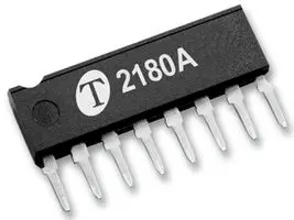
Yes. Pin one is the pin closest the dot or cutout in the packaging. Pin 4 is the 4th one from the left in this picture.
42585322.jpg


thanks Metoo2,

have taken pin 4 out of all of the THAT2180 now, have changed the 7815 and im getting 15v on the right hand leg but at the +15v rail im getting -1.015v now?
and the LED doesnt come on at all? dont really understand why at the 22r resistor it reads -1v now?? could it be a leaky 22uf on the other side of the 7815? could the relay be at fault?
i need more training on how to understand what exactly is going on here!!! :)

regards

Spence.
 
Spencerleehorton said:
thanks Metoo2,

have taken pin 4 out of all of the THAT2180 now, have changed the 7815 and im getting 15v on the right hand leg but at the +15v rail im getting -1.015v now?
and the LED doesnt come on at all? dont really understand why at the 22r resistor it reads -1v now?? could it be a leaky 22uf on the other side of the 7815? could the relay be at fault?
i need more training on how to understand what exactly is going on here!!! :)

regards

Spence.
Well the problem definitely looks like it's related to your PSU.

Which side of the 22R resistor is at -1V? The leg connected to the 7815, or the leg connected to the 7812?
What is the voltage at the other leg (then you can work out the current draw I = v1-v2/22)?
What are the voltages at both legs of the 10R resistor feeding the 7815?

My first guess is that you are drawing too much current = likely a short circuit to ground somewhere on either the +12V or 15V power rail.
Second guess would be incorrect component orientation e.g. electrolytic cap or diode the wrong way around.
Third guess would be regulator latch up.
 
ok,

the 10r resistor from the 7815 measures 23.14v, the 22r is -1.121v same as +15v rail.
The electrolytic 22uf + side is 14.99v
other side of 22r is -0.964v

all diodes are correct way and all electrolytics are correct way!

regards

Spence.
 

Latest posts

Back
Top