GSSL HELP THREAD!!!

GroupDIY Audio Forum

Help Support GroupDIY Audio Forum:

This site may earn a commission from merchant affiliate links, including eBay, Amazon, and others.
Spencerleehorton said:
ok,

the 10r resistor from the 7815 measures 23.14v, the 22r is -1.121v same as +15v rail.
The electrolytic 22uf + side is 14.99v
other side of 22r is -0.964v

all diodes are correct way and all electrolytics are correct way!

regards

Spence.


There's multiple 22uF caps (6 off), so it might help if you post a picture with the location of your measurements attached.

For the positive rails that'd be locations A-E and for the negative rails A'-E' all relative to 0V signal ground.

ssl_psu_measurement_zps80ff7a45.png


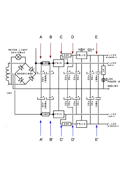
OK If I've understood you correctly. The input to the PSU at point A is around 23V which looks OK.

The current on the 10R is (point A - Point B )/10 = (23.14-22v) /10R = 114 mA.
Looks quite high but not unreasonable depending on lamps etc.

The output of the 7815 is +15V (22uF cap connected to 7815), which is correct.

But the 15V rail is measuring low @ point C = -1.121v.

So it looks like there's a dry solder joint or broken track around that area, or you've forgotten a jumper.

Suggest you trace the tracks and check where the voltage drop occurs.
 
well how embarrassing!! i dont mind admitting im a schmuck!!!
one end of the rails i hadn't soldered, and also the 7815 bit of the pcb rail had come away so i put a jumper to where it should go!!
hey presto all working fine, somehow all the chips are fine!!

thanks for all your advise, much appreciated.

regards

Spence.
 
Hey guys, got a friends unit on the bench and helping to him troubleshoot it. Its a pretty clean build, but for reasons I'm  yet to find, its not passing any audio. Voltages are looking good... 12V and 15V rails check out ok.
I've got through all the obvious things
- checked for correct components - all resistors are correct and all caps have the polarity the right way around.
- swapped out all opamps and VCAs with known working ones
- checked XLR wiring - I suspected dodgy molex connections so i've redone all those, but to no avail.
- checked for shorts around the input an output opamp sections but none that I can see

So after spending a few hours on this i'm a bit stumped. I've yet to build a unit that refuses to pass any audio. I know its like finding a needle in a hay stack, but any pointers on where to begin??

 
Only time I've had this on a unit that had all voltages (plus AND minus) on all opamps and with verified VCA's, was one where the builder for some reason had decided to use female XLR's for output, male for input.

Probably not that in your case: Try tracing signal through input debalancing stage, to VCA current-input resistors (you can't measure on vca input directly), to output stage.

Jakob E.
 
Hi Guys,

Got a GSSL with an amount of distortion on higer compression and even higher on fast attacks. Should there be ANY distortion like this? I wouls say it's approaching 10-20% and it's harmonic- not clipping.
 
gyraf said:
Only time I've had this on a unit that had all voltages (plus AND minus) on all opamps and with verified VCA's, was one where the builder for some reason had decided to use female XLR's for output, male for input.

Probably not that in your case: Try tracing signal through input debalancing stage, to VCA current-input resistors (you can't measure on vca input directly), to output stage.

Jakob E.

Hi Jakob,

Thanks for your help. I've gone through and measured all the ICs again and checked against voltages in the schematic:

For both the L & R Input 5534 opamps I have -15V on pin 4 and +15v on Pin 7 which is correct I believe
For both the L & R Output 5532 opamps I have -15V on pin 4 and +15v on Pin 8 which is correct I believe
On both Left and Right VCA sections I have -15V on Pin 4 and +15v on Pin 7

When I measure TL072 and TL074 my measurements start to deviate from the schematic:
- On TL072 Pin 8 I have +12V which appears correct,  however on pin 4 I have a negligible reading when I should be seeing -12V ?
- Similar situation on TL074 I don't have -12V and +12V where I would expect to when looking at the schematic

Am I onto something? Thanks for your help
 
Hi Frazzman,

Pin 4 of the TL072 is right off the 79L12 reg. Check continuity between pin 4 and the output of the 79L12
 
jwhmca said:
Hi Frazzman,

Pin 4 of the TL072 is right off the 79L12 reg. Check continuity between pin 4 and the output of the 79L12

Hi jwhmca, thanks for the reply. I have continuity between pin 4 and the reg. Am I mistaken for thinking I should be measuring 12V on pin 4? Thanks
 
Do you have -12VDC coming out of the 79L12?

If so double check the solder at the TL072... maybe it's not really solder into the PCB?
 
frazzman said:
..- On TL072 .. however on pin 4 I have a negligible reading when I should be seeing -12V ?
Remove the short at the 79L12 (a short here will cause overheating of the 22R resistor from latest pcb revision or the 10R resistor from previous pcb revisions) or the short further downstream this -12V rail. Double check polarity of electrolytic caps, connecting to this -12V rail.
 
Harpo said:
frazzman said:
..- On TL072 .. however on pin 4 I have a negligible reading when I should be seeing -12V ?
Remove the short at the 79L12 (a short here will cause overheating of the 22R resistor from latest pcb revision or the 10R resistor from previous pcb revisions) or the short further downstream this -12V rail. Double check polarity of electrolytic caps, connecting to this -12V rail.


Thanks Harpo

Upon closer observation the 79L12 regulator is heating up, too hot to touch within a few seconds of power on

- I've checked for the regulator shorting between pins, even went as far as cutting the pcb traces and soldering jumpers in case theres any traces on the PCB that I can't see
- checked polarity of all electrolytics and they are fine

Any idea what could be causing the regulator to heat up like that? Clearly a short, but not in the obvious places as far as I can tell
 
Hi frazzman,

By coincidence, I seem to have the exact same issue - negligible voltage reading at all the points where I should expect -12V and 79L12 is too hot too touch.

Please let me know how you go...

I'm new to PCB troubleshooting so if anyone else could chime in with suggestions, that would be great. Where should I look for shorts.

Also is it possible that the 79L12 is simply faulty? Are these components easy to kill or pretty hardy?

Edit: The 22R resistor is hot to touch also
 
Everland said:
Hi frazzman,

By coincidence, I seem to have the exact same issue - negligible voltage reading at all the points where I should expect -12V and 79L12 is too hot too touch.

Please let me know how you go...

I'm new to PCB troubleshooting so if anyone else could chime in with suggestions, that would be great. Where should I look for shorts.

Also is it possible that the 79L12 is simply faulty? Are these components easy to kill or pretty hardy?

Edit: The 22R resistor is hot to touch also

Hi Everland, I've built about 10 of these and never seen this issue so I am just as confused as you are. The regulators are pretty hardy on my experience, I've only ever really killed I opamps before, they don't take too kindly to excessive voltage. I tried replacing the 79L12 regulator but still have the same issue. I thought the issue was due to shorting between pins 2 and 3 but that's not the case. I surely think we have a short in that area but I can't find one...check correct orientation of your 22uf caps around the regulator, mine were fine... Let me know how you go
 
Thanks Frazzman.

Yep, same for me - I've checked for a short between pins 2,3 on the 79L12, nothing there.
Checked the orientation of all those 22uf electrolytics and they are all fine.
Checked for shorts further downstream on that 12V rail, nothing!

 
Everland said:
Thanks Frazzman.

Yep, same for me - I've checked for a short between pins 2,3 on the 79L12, nothing there.
Checked the orientation of all those 22uf electrolytics and they are all fine.
Checked for shorts further downstream on that 12V rail, nothing!

Yep exactly the same here. Ill take a look again with fresh eyes. I take it you're not passing audio as well? That was the symptom of my fault but then after measuring the voltages it becaame apparent that something on the 12V rail wasn't right. The weird thing is that the 12V measurements on other parts of the PCB are ok, like on the back of the PCB where there are the points with 12V marked next to them
 
Yeah, the unit wasn't passing audio at all with all VCAs and opamps in place.

I did an experiment though with leaving in all the input/output opamps and the VCAs with their associated opamps, just removing the sidechain opamps and VCA.
The unit would then pass audio although it sounded like it was compressing it in a strange way... not surprising I guess given that the main VCAs would not have been seeing any CV at all?

On my unit all the +12V points are fine, it's only where you would expect -12V that there is a problem... are you saying that you're getting -12V at some points too?
 
Everland said:
Yeah, the unit wasn't passing audio at all with all VCAs and opamps in place.

I did an experiment though with leaving in all the input/output opamps and the VCAs with their associated opamps, just removing the sidechain opamps and VCA.
The unit would then pass audio although it sounded like it was compressing it in a strange way... not surprising I guess given that the main VCAs would not have been seeing any CV at all?

On my unit all the +12V points are fine, it's only where you would expect -12V that there is a problem... are you saying that you're getting -12V at some points too?

Sounds like we have exactly the same problem. Come to think of it +12 measures fine but -12 would be bad everywhere... ill persevere!  Let me know if you find a solution
 
Back
Top