Mowenw said:
you are entering into personal troubleshooting here on the forum
Indeed, I am.
Will check the pics when they are here, then move to the next step.
As per trouble shooting further on. I feel like you are insisting on answers "whats wrong, dont answer my post if you dont have the definitive answer" etc type of rhetoric. I find it difficult to handle, to be honest. (Your very first post in the trouble shooting guide reflects this, and although its fine, but for the way I trouble shoot, I can't find a way through it).
I feel ike there is a better way, and it must also be stressfull for you, for example, you have posted a time spent on 70 hours for trouble shooting just 3 weeks after I shipped the kit. This is a very long time to spend without getting to the goal, and if we add some build time, it sounds like you've turned this into a full time job. I think the time could be spent more productively.
I feel like you rule out possible errors, but some of the issues you rule out are very likely to be the root of your problems. I am very confused about where youre at despite your lists during your process (maybe Im just slow!), but the current problem seems to be getting the unit to interact.
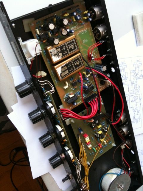
I would check the soldering, measures voltages on the ICs in the side chain, check the connectors, and very importantly, check the bypass switch set-up (VERY common to make mistakes on this). The way I understand it, you have ruled out over half of these options, not by reporting correct measurements, but by speculation (can't imagine there are any soldering problems, cuz I looked at it, Can't imagine theres a problem with the bypass switch, since its a standard mod etc) Its not productive for finding your error/s.
Maybe I am not reading you right, but if thats the case, I just dont "get you" well enough to help you it seems.
By your own account, you have started over and removed/resoldered all your components, so now we start over. And hopefully, others will benefit from the process being open. With you, I am not interested in doing it by mail. I find it best that others, others who may understand your trouble shooting philosophy better, have a chance to participate.
So, I propose we get back to what this thread is really intended for.
Gustav


![Soldering Iron Kit, 120W LED Digital Advanced Solder Iron Soldering Gun kit, 110V Welding Tools, Smart Temperature Control [356℉-932℉], Extra 5pcs Tips, Auto Sleep, Temp Calibration, Orange](https://m.media-amazon.com/images/I/51sFKu9SdeL._SL500_.jpg)


