GSSL HELP THREAD!!!

GroupDIY Audio Forum

Help Support GroupDIY Audio Forum:

This site may earn a commission from merchant affiliate links, including eBay, Amazon, and others.
Ok. Checked out.

It is still not completely happy. I'm not getting equal level from the channels. Right channel is slightly quieter. Also, when I turn the threshold clockwise the compression kicks in but it sounds distorted and it's level compared to when in bypass with no compression is a lot quieter. The level of distortion I'm getting through now is nothing compared to how it was before (there has been some improvement).

So yeh. I've switched around the IC's and VCA's with no effect. Might it b e worth changing out the regulators ?

 
Ok. On a second checking I would probably say that everything is working ok apart from the make-up pot.

Are there any typical feck-ups with regard make-up pots?

MAtt.
 
Where the heck can I find the 10 pin molex connector harness?  I have the board male end soldered in and I've been searching forever to find the connector and harness to tie into the front board (mine didn't come with one) thanks!
 
Mowenw said:
Ok. On a second checking I would probably say that everything is working ok apart from the make-up pot.

Are there any typical feck-ups with regard make-up pots?

MAtt.

Still something wrong in the bypass switch set-up...

Gustav
 
ssl.jpg


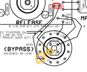
So i've decided to focus a little bit on the bypass switch because in my unit i didn't connect the two points that i circled in red, together. Should they be connected together?

If so, then what is the point of taking them to the switch (marked in orange)? I don't get it.
 
Don Solaris said:
ssl.jpg


So i've decided to focus a little bit on the bypass switch because in my unit i didn't connect the two points that i circled in red, together. Should they be connected together?

If so, then what is the point of taking them to the switch (marked in orange)? I don't get it.

No,  red circled points don't need to be connected on the pcb. If you wire the lorlin switch as shown in the picture, everything is fine.
Bernd
 
bernbrue said:
No,  red circled points don't need to be connected on the pcb. If you wire the lorlin switch as shown in the picture, everything is fine.
Thanks! Just as i suspected. Also checked the wiring of the bypass switch and it is ok in my unit, as per schematic.
 
Screenshot%20from%202015-04-17%20230838.jpg


Ok it is getting better. I've made unity gain mod and the voltages are now more less ok. Just few more bugs left. I am submitting a video (decided to delete my previous post since it is obsolete now):

https://www.youtube.com/watch?v=YzWeh47G8LM

So i connected 2Vpp sine wave at the input. At the output i'm getting around 2Vpp when Threshold is set to around 0 and Make Up set at 0. So far so good. But...

  • As you can see when i move threshold positive, voltage at the output goes up.
  • Same thing happens with ratio switch. As i move from 1:2 to 1:10 ratio, voltage at the output increases as can be seen.
  • And the same thing happens with the Attack switch. As i move it toward Slow, the voltage at the output increases.

I'm still reading thru this large thread, i've noticed some ppl had similar problem but that's because they had DC leakage at point "C" which i don't have.  So i'm a bit confused now.


Threshold must be set fully clockwise, in 12 o'clock position the item already starts to compress. For me the compressor seems to behave fine. Feed it with a drum loop and learn/listen what it does.
Bernd
 
Yup already tested it with some drums seem to compress. Comp seems to be working as you described it with 0 position already compressing.

I assume the increase of level that we can see in video above when setting Ratio 1:2 to 1:4 to 1:10 has to do with some sort of gain compensation?

So the only mystery left is the Attack switch - why on earth does its signal level increase as i move it from fast to slow?
 
:)

I'm obsessed with technical details. I will probably spend a week calibrating everything i can, starting with meter, THD level, etc.
 
Well, I'm a musician. As soon as the meter starts to dance to the rhythm and my ears love what they hear the built is done.  Only when there are obvious mistakes or some kind of strange behaviour I dig out my measuring instruments. Enjoy it.
Bernd
 
Ok unit tested and seems to be working. I was surprised to see levels of both channels near equal with some minor offset like 0.1 dB. Wow! I was expecting one channel will require trimming.

First task is to replace bypass switch with 25k lin pot which will be used to calibrate the meter sensitivity.  So that it can work with different ranges without need to open up the unit and replace resistor each time. Either pot or rotary (with several resistors) for some classic scale ranges. That way the unit can be used for super precision work i.e mastering 0-6dB meter scale all the way to extreme 0-24dB for some heavy drum processing - on the same meter.

Interesting to see, this meter that my unit has requires way more than recommended 2k ohm. In fact it is in 17k ohm for 20dB needle movement.
 
I'm looking for a source for the Sifam knobs in the US. I've found two suppliers:

1. Canford  in the UK - a bit pricey with shipping
2. Selco in the US - $50 min order

Is there anyone else?
 
Hi,

I have a question regarding the Lorlin switches. I searched throughout the thread and I found some people saying they bought some non-shorting ones and other saying shorting was the way to go. Also some people saying non-shorting was ''OK''..  but is shorting better? I am kind of confused as to which type I need.  MBB or BBM ? Thanks !

- Joel
 
johnnyscotch said:
Harpo said:
Lorlin end-stop washer set to position 5 ?
again, can you elaborate? I followed the build guide instructions pretty faithfully, maybe I missed something?

JohnnyScotch, did this end up being the problem with your crunchy auto-release? I'm experiencing the same thing in that position. I'm going to take a look at my pins again this week.
 
Back
Top