chrispbass
Well-known member
Hi all, had a few years lay off from building gear (long story) and have all my projects and components back in one place.
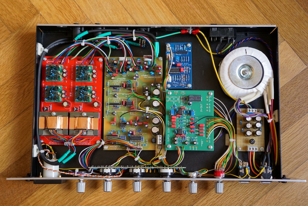
My gssl is nearing completion and just need a quick confirmation reg the hairball meter. Are the inner connectors for the meter and the outer(spade) connectors for the leds? Also, if running the LEDs off the rails, what resistor would be needed? Was thinking about 330r ?
Thanks guys")
My gssl is nearing completion and just need a quick confirmation reg the hairball meter. Are the inner connectors for the meter and the outer(spade) connectors for the leds? Also, if running the LEDs off the rails, what resistor would be needed? Was thinking about 330r ?
Thanks guys


![Soldering Iron Kit, 120W LED Digital Advanced Solder Iron Soldering Gun kit, 110V Welding Tools, Smart Temperature Control [356℉-932℉], Extra 5pcs Tips, Auto Sleep, Temp Calibration, Orange](https://m.media-amazon.com/images/I/51sFKu9SdeL._SL500_.jpg)