GSSL HELP THREAD!!!

GroupDIY Audio Forum

Help Support GroupDIY Audio Forum:

This site may earn a commission from merchant affiliate links, including eBay, Amazon, and others.
angelo2979 said:
Hi! I've just finished another Gssl, I did some testing today and everything looks working...except for a problem in the left channel. Could you help me figure it out?

The left channel is rolling off bass below 100hz . Actually at 100hz the Left channel is 0.5 db quiter, and  down at 20Hz it gets 6db quiter then the right channel! Testing in pro tools with some white noise and sinusoides...

Also, with no audio signal passing, noise is fine in the Right channel (linear, -130db or so), but the Left shows 22db more noise peaking at 40/50Hz. It's not audible but it's there, and maybe related to the rolloff above....

Everything else works fine!

Do you have any suggestions of what should I look for before I open it?
Thanks!


If you don't get any answers here, I think this would be a good question to post in the Lab section too..Like low frequency roll off in one channel or something as a title....... Could be helpful in general to hear suggestions ...

Good Luck!
 
angelo2979 said:
The left channel is rolling off bass below 100hz . Actually at 100hz the Left channel is 0.5 db quiter, and  down at 20Hz it gets 6db quiter then the right channel! Testing in pro tools with some white noise and sinusoides...
Most likely cause is a bad/no solder connection or bad cap at one or both of the left channel 22uF input cap(s) with the 100nF in parallel, so only the 100nF remains in circuit. This Hpf in Hz is set at 1/(2*PI()*R*C) with PI()=3.14159...., R in ohms = 22000 and C in Farad = 0.0000221 or 22.1E-6. Your -6dB at 20Hz figure could be caused by a 209nF cap value on paper in this context.
Next possible cause is a faulty 22uF cap, connecting to pin6 of the balanced line receiver NE5534. These connect to a 27K in parallel with a 47K to the virtual ground nodes of the audio- and sidechain VCAs. Same Hpf formula as above, you do the math.
Next possible cause are the output stages 100uF caps with 100nF in parallel, with 47K and the input impedance of the following piece of connected gear in parallel that might took a kick in the butt from accidently activated phantom voltage of a A/D-converter that sometimes come with mic input stages. Same Hpf formula as above, you do the math.

[rant mode on] Revision 9 and still no parts designators. Schematic errors and pcb inconsistancies are a 2-digit number with 1st.number not a 1 still not beeing corrected, ... [/rant mode off]

Also, with no audio signal passing, noise is fine in the Right channel (linear, -130db or so), but the Left shows 22db more noise peaking at 40/50Hz. It's not audible but it's there, and maybe related to the rolloff above....
A 50Hz peak could be induced mains frequency from a piece of gear above/below your racked gssl or a radiating lamp /halogen spot into your gssl with lid open. Any audio wires close to primary/secondary AC supply wires? A ground loop probably would have effected both l/r channels, so lesser likely.

Do you have any suggestions of what should I look for before I open it?
Wild guessing, there is no way around opening the unit in order to see/measure what's going on.
good luck
 
Many thanks!

That was exactly the kind of info I was looking for before opening the thing.
I'll report back any solutions or further dilemmas  :)

 
hi everyone!
finish my gssl rev#7and i got distortion sound at low frequency and the 78l12 is running very hot

i checked every possible thing :  the voltages are ok , i´m getting -15/15v and 12/-12v on the board marks. diodes are ok,
changed the regulators. trafo is 16v.

i search on the post, and i found similar problems, but there was no solution answer.

any idea what it might be?
any ideas?
I would be very grateful
thanks a lot!
 
pabloyorke said:
finish my gssl rev#7and i got distortion sound at low frequency and the 78l12 is running very hot
Most likely bypass switch (whatever your switch might be) hooked up wrong between wiper of makeup pot and 620K resistor, shunting the 78L12 down to self protection mode when wiper is set towards the +12V rail with switch throw position connected to 0 V reference voltage. The makeup pot might fail this way as well.
Electrolytic caps at the +12VDC rail fitted with reversed polarity might be the next reason why. The vreg will not deliver enough current to blow the cap for an easier identification of the culprit, so you'll have to double check yourself.
Good luck.
 
Harpo said:
Most likely bypass switch (whatever your switch might be) hooked up wrong between wiper of makeup pot and 620K resistor, shunting the 78L12 down to self protection mode when wiper is set towards the +12V rail with switch throw position connected to 0 V reference voltage. The makeup pot might fail this way as well.
Electrolytic caps at the +12VDC rail fitted with reversed polarity might be the next reason why. The vreg will not deliver enough current to blow the cap for an easier identification of the culprit, so you'll have to double check yourself.
Good luck.

hi Harpo
thanks for the reply
i´ll check again following your instructions
i got some new regulators too, from other brand, just to check
i´ll post the results soon
thanks again!
 
pabloyorke said:
hi Harpo
thanks for the reply
i´ll check again following your instructions
i got some new regulators too, from other brand, just to check
i´ll post the results soon
thanks again!

Solved!
I was a bad NE5534

Found the solution reading the post #4199 (this post is pure gold!)
I follow the steps and founded the problem
thanks a lot!
 
+1 on Harpo's comment!


@ pabloyorke:


Your post does not cover what the real issue was,but most likely not a bad NE55xx opamp.
So your post does not help anybody running in similar trouble,exept of making this thread even more confusing.
Would you be so kind and tell what else you have done to "fix" it?


Udo.
 
When using the rev #7 pcb with onboard power transformer, can i still use a switch to enable/disable hpf in the sidechain? it seems that a jumper is not implemented in that version.
 
weiss said:
When using the rev #7 pcb with onboard power transformer, can i still use a switch to enable/disable hpf in the sidechain? it seems that a jumper is not implemented in that version.

Just check where the jumper is placed in the circuit, and "tap in".

Gustav
 
I have a working unit where i am planning to put real gold cans dbx202 in place of the emulation ... i removed the 5534 and the that's but some resistors and capacitors left , should i have to remove them ? any other mod to make the dbx202 work ? I was unable to find clear infos about that even if i see a lot of builds using the 202c
 
Hi!
Just got hold of a set of original SSL VCA cards taken from a working FX G384 unit. Not the DBX ones but the newer onew I guess SSL is manufacturing on there own. I'll add some pics below. Does anyone have any experience using these for this build?

Seens I'm only have two, can I use a DBX or THAT VCA for the third sidechain VCA?


Attachments

  • s-l400.png
    s-l400.png
    328.6 KB
Thanks for answer !!!  :( ... i found the info alone ! Helpful thread anyway, so, for all planning to mod a gssl with 202c dbx, all i can say is that it is worth it despite what some will claim, the 202c seemed to be more "organic" than the substitute. I just installed sockets and removed the That's chip and the 5534 ... et voilà ! A much better compressor IMHO. ... but hey ... it's the standard build here ... shut your mouth !
 
Well seems like I jump to conclusion about my post earier regarding the G384 VCA chips. Still waiting for there arrival but had a closer look at the pics the seller supplied in the auction and there is a DBX marking on them so not the new THAT VCA made for the current line of bus compressors. Since this is my first build I didn't know the looks of the DBX 202 cards and assumed that all DBX 202 there cans :)

So guessing these perhaps are from an old greyfaced g384 after all? according to some google image searching these are probably  DBX 202 cards but need to examen them in more closely on arrival to confirm what version of the DBX 202 cards this is.

Anyone know if there where any other DBX cards then the DBX 202X used in the FX 384?
 
hi, newbie here, got a working gssl from a friend but i have a problem when using it on my mixer inserts:

pluggin the gssl to the main inserts of my mackie 1642 vlz3 lowers the volume by around 10dB.

I have checked and it is not a problem of the 15K/27K resistors as they are 27K.

If i connect the gssl in series with the mackie ( master outs -> gssl -> speakers) there is no gain loss.

If i plug it in the inserts, there is about 10dB loss. I believe is something with the cables and wiring but I can't figure out what. If someone has an idea, it would be much appreciated!

mackie insert tip is send, ring is return.

cables are both identical 1/4" to 2 XLR (y cable).

1/4" tip --> xlr1 pin 2
1/4" ring --> xlr2 pin 2
1/4" sleeve --> pin3 on both xlrs

pin1 on both xlrs  --> shield
 
Manellus said:
hi, newbie here, got a working gssl from a friend but i have a problem when using it on my mixer inserts:

pluggin the gssl to the main inserts of my mackie 1642 vlz3 lowers the volume by around 10dB.

I have checked and it is not a problem of the 15K/27K resistors as they are 27K.

If i connect the gssl in series with the mackie ( master outs -> gssl -> speakers) there is no gain loss.

If i plug it in the inserts, there is about 10dB loss. I believe is something with the cables and wiring but I can't figure out what. If someone has an idea, it would be much appreciated!

mackie insert tip is send, ring is return.

cables are both identical 1/4" to 2 XLR (y cable).

1/4" tip --> xlr1 pin 2
1/4" ring --> xlr2 pin 2
1/4" sleeve --> pin3 on both xlrs

pin1 on both xlrs  --> shield

The GSSL appears to be working fine if in series as the master outs are balanced. The inserts on the Mackie are unbalanced, so that is where your gain loss is. This is not a GSSL issue.

Thanks!

Paul
 
Hi all. Yet another plea for help here.

I bought a GSSL kit from Gustav at pcbgrinder.com. Very happy with the kit and the case is just gorgeous. Had a lot of fun bulding it. Until I turned it on, that is. Everything lights up and both the 15V and 12V rails are where they should be more or less (see below for more voltage readings). The meter responds to input and the threshold control seems to be working as it should. In short, everything appears to be fine, except for the minor detail that I can't seem to get any sound from it, neither while bypassed or when compressing. With the unit turned off and with my mixer line and master pushed up all the way I get some traces of the signal, but when I turn it on, it disappears. Very strange.

Voltage readings:

Marked on silkscreen
+15V: 14.912 V
- 15V: -15.102 V

Marked on the solder side:
+12V: 12.012 V
-12V: -11.838 V

5534 pin from furthest towards the rear of the unit to nearest the front panel:

1
Pin 1: 0.00 V
Pin 2: -0.18 V
Pin 3: 0.00 V
Pin 4: -15.09 V
Pin 5: 0.00 V
Pin 6: -0.17 V
Pin 7: 14.92 V
Pin 8: 0.00 V

2
Pin 1: 0.00 V
Pin 2: -0.17 V
Pin 3: 0.00 V
Pin 4: -15.09 V
Pin 5: 0.00 V
Pin 6: -0.16 V
Pin 7: 14.92 V
Pin 8: 0.00 V

3
Pin 1: 0.45 V
Pin 2: 0.44 V
Pin 3: 0.00 V
Pin 4: -15.09 V
Pin 5: 0.00 V
Pin 6: 0.43 V
Pin 7: 0.42 V
Pin 8: 14.92 V

4
Pin 1: 0.42 V
Pin 2: 0.42 V
Pin 3: 0.00 V
Pin 4:-15.09 V
Pin 5: 0.00 V
Pin 6: 0.41 V
Pin 7: 0.40 V
Pin 8: 14.92 V

5532
Right VCA
Pin 1: 0.00 V
Pin 2: 0.03 V
Pin 3: 14.92 V
Pin 4: 0.00 V
Pin 5: 0.00 V
Pin 6: 0.03 V
Pin 7: 0.00 V
Pin 8: -15.09 V

Left VCA
Pin 1: 0.00 V
Pin 2: 0.03 V
Pin 3: 14.92 V
Pin 4: 0.00 V
Pin 5: 0.00 V
Pin 6: 0.03 V
Pin 7: 0.00 V
Pin 8: -15.09 V

TL072
Pin 1: -0.01 V
Pin 2: -0.09 V
Pin 3: 0.00 V
Pin 4: -11.85 V
Pin 5: 0.00 V
Pin 6: 0.97 V
Pin 7: 0.01 V
Pin 8: 12.01 V

TL074
pin 1: -0.48 V
pin 2: -0.56 V
pin 3: 0.00 V
pin 4: 12.01 V
pin 5: 0.00 V
pin 6: -0.52 V
pin 7: -0.52 V
pin 8: 0.00 V
pin 9: 0.00 V
pin 10: -0.02 V
pin 11: -11.85 V
pin 12: 0.00 V
pin 13: -0.57 V
pin 14: -0.20 V

The board


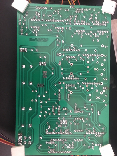
Main board from below


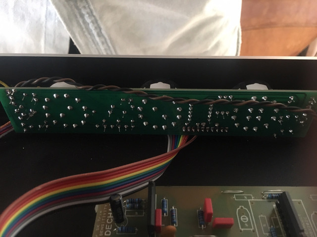
The control board


Switches (this photo is not very informative, but the others were even worse)


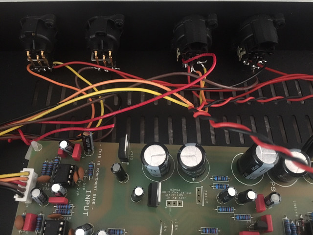
XLR outputs (I used seperate wires that meet at the chassis ground)


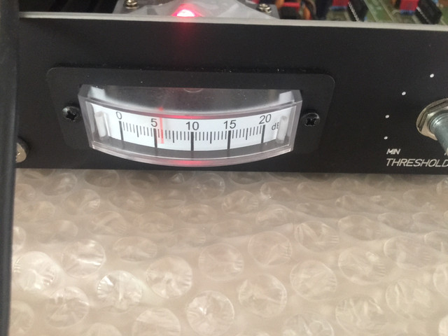
The meter showing compression


Does anyone have any idea what the problem might be? I'd be very grateful.

Thanks!
 

Attachments

  • IMG_4704.JPG
    IMG_4704.JPG
    1.1 MB

Latest posts

Back
Top