


bobtheninja
Active member
- Joined
- Sep 5, 2010
- Messages
- 31
Thanks for your reply! I took off the bottom casing and took a look, comparing it to the general wire guide by Gustav, but I couldn’t see what was wrong from my wiring to his guide. This is what I have:
XLR out 1
Pin1 red
Pin 2 orange
Pin 3 yellow
XLR out 2:
Pin 1 red
Pin 2 brown
Pin 3 black
XLR in 1:
Pin 1 red
Pin 2 yellow
Pin 3 orange
XLR in 2:
Pin 1 red
Pin 2 black
Pin 3 brown
Red goes to chassis earth.
And a picture:
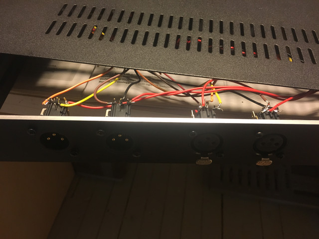
Is this incorrectly wired? If so that makes me very happy (and slightly embarassed). Thanks again!
XLR out 1
Pin1 red
Pin 2 orange
Pin 3 yellow
XLR out 2:
Pin 1 red
Pin 2 brown
Pin 3 black
XLR in 1:
Pin 1 red
Pin 2 yellow
Pin 3 orange
XLR in 2:
Pin 1 red
Pin 2 black
Pin 3 brown
Red goes to chassis earth.
And a picture:
Is this incorrectly wired? If so that makes me very happy (and slightly embarassed). Thanks again!


") Back to it!
Back to it!