GSSL HELP THREAD!!!

GroupDIY Audio Forum

Help Support GroupDIY Audio Forum:

This site may earn a commission from merchant affiliate links, including eBay, Amazon, and others.
Just wondering what gauge wire to use between the boards / headers ect;

Is 22 AWG OK, & should I use audio cable from the XLR's to & from the board? I assume that would be better for my signal? What's the right size wire for the PT?

I KNOW this is a stupid question

:oops: but I've only worked on tube amps before :roll: & it's always best to check these things....! Just in case!
 
The size of wire from the control board to main pcb is not important. Audio is not on that wire. 22 should be fine. Yes, use audio wire to XLRs. What is PT?
 
yeah 22 awg is fine. Some people use solid core cat 5 wire (just strip the wires out of the jacket) I've tried it and the problem is that it's a little prone to breaking but it's definitely cheap and you get multiple colors.

For people in the US, here is a HUGE time saver:

http://www.allelectronics.com/cgi-bin/item/CON-2410/search/10-PIN_CONNECTOR_W__HEADER,_.1"#34;_SPACING_.html

And for the I/O yes shielded cable is a good idea.
 
Hi,

I just finsished assembling my GSSL, which is my first real DIY project. Thanks to everyone on this forum for all the posts and help, I'm a complete newbie at this and would have never attempted or gotten so far without this forum.

I tried to power up the compressor without any of the ICs in. The power LED came on and nothing smoked, but when I measured the 15v and -15v rails, I got 29.8v and -29.8 volts. The 12v rails read plus and minus 13.4v.

I read in the thread that the rails can be higher than 15v without any ICs to draw the load, but I would guess this is way to much.

Should I throw the ICs in and see what happens or start looking for mistakes in the power hookup or the components?

Any help will be greatly appreciated.

Thanks,

Tarek
 
Hi Tarek,

If you read back through this thread, you'll find that you're not the only one with this problem. The simple answer is that the 78XX/79XX regulators needs some load to start regulating. Throw in the IC's (observe orientation on each and every one!!!!), and retest. My guess is that you're fine..

Jakob E.
 
Jakob,

Thanks for the quick response and the whole project. It is my electronics 101 course. All of your DIY projects and instructions are such an incredible resource, I feel like I should be paying you for them; Thank you so much. I put my ICs in and got it running. Did some tests, and it sounds good. I'm going to take it into the studio tommorow and really check it out.

It turns out that I was testing it wrong ':oops:'. If this was on the thread before and I missed it, I apologize. When you go from the +15v rail to the -15v rail you get +30v or -30v. Despite the embaressment I thought I'd put this up in case anyone else has the same problem. I hope I didn't damage anything by doing it. It sounds O.K.

When I paint my case and figure out some silkscreening for the front, I'll put up some pictures.

Thanks,

Tarek
 
Has anyone used this Toroid for their GSSL clone? The Amveco toroid is out of stock at Digikey.

Avel Lindberg
Load (VA): 30
Secondary V: 15 + 15
Current Load (A): 1.00
Avel P/N: Y236103

I'm using Greg's Part list and it calls for a 15V-0-15V, 0.832A -- 25VA Toroid. Is this too much of a difference?

Thanks!
Joe
 
[quote author="jlearman"]Has anyone used this Toroid for their GSSL clone? The Amveco toroid is out of stock at Digikey.

Avel Lindberg
Load (VA): 30
Secondary V: 15 + 15
Current Load (A): 1.00
Avel P/N: Y236103

I'm using Greg's Part list and it calls for a 15V-0-15V, 0.832A -- 25VA Toroid. Is this too much of a difference?

Thanks!
Joe[/quote]

http://www.groupdiy.com/index.php?topic=208184&highlight=lindberg#208184

Search is your friend....

You might even be able to find a post (from me) which describes the color coding of the avel and how to wire it.

:thumb:
 
So..i hope this is my last question about my point2point ssl-project..
metalwork is done only grounding left.. since i didn´t use the pcb ( did it on some experimental-board , as the sidechain mod and external psu ) , I went star grounding on the board , leading to one cable and have more grounding cables from sidechain release , makup-gain-pot , psu and transformer.. i wanted to go with all this cables to one central grounding point at the chassis ( where power ground is also connected ) i wanted to connect all the xlr pin 1
there also..so my question is if this is possible in my case .. i have looked at the layout of jakobs pcb , where it seems electrically the same for example directly connecting all xlr pin 1 together and not connecting the out 0 in this case.. as they are shorted on the pcb anyway...this is my first diy and i learned so much in doing it this way , so i hope that i am right with my grounding thoughts...

greets & thx...
axel
:roll:
 
Hi
i am about to finish my 1st GSSL, and I'm not relay sure that this is a problem but:
all sockets (unpopulated) read expected voltages except for the side chain VCA... Negative reads ~8.5VDC and positive ~12VDC...I'm a bit confused over this.The voltage is ~12 VDC up to 3k9 resistor and it drops to ~8.5VDC after the 3k9 resistor.Is this meant to be this way?Can not find any bad solder, parts miss direction or wrong value parts around this area of the PCB.I had the board made locally using Jakob's layout revision 8, from Gyraf's site...This happens regardless of connecting-disconnecting the control board...
THANK YOU
 
Hi Syn,

I've had numerous voltage irregularity issues with my second-hand GSSL board. It can be very hard to determine the problem. But the sidechain should have both + and - 12 volts, obviously, so you do have a problem somewhere if those voltages are not present.

Check your regulators. That's where almost all of my voltage problems were coming from. I also had lifted pads and broken traces. (One lifted pad was under a regulator! Grrr.)

It's not fun to troubleshoot. But the power supply is easy to check. Measure the voltage at the destination sockets and if it's not correct work backwards. Measure at the output of your regulators too. You'll find the problem.

Checking voltages at the sockets should be a standard first power-on test in everyone's GSSL build.

We published the correct power voltages, and identified which pins you find them on, many pages back in this thread. But it is easy to figure out what they should be. Just look at the documentation.

However, there were some other weird smaller voltages at other (non-power supply) pins which apparently are correct, so you might want to review the thread if you're concerned about those. Otherwise, just check your power supply pins at each chip.

It's a simple little circuit, but the board is quite difficult to follow traces and figure things out on -- made especially hard because parts are not numbered.
 
I have changed 3k9 to 5k1 as on the THAT app. notes. and i have further drop on the leg 5 of another ~0.5VDC.I re-searched the thread and found that others had measured the similar voltage drop after 3k9-5k1 on the side chain, and also Jakob's statement that THAT should be O.K.As far as i get it that resistor is current limiting in that situation and VCA would operate from 4-20VDC anyway.I was just confused as all other voltages were in the range of what i thought they would be...
Big thanks to Jakob and Tommypiper for replaying.
Still have to hook it up all tomorrow...
:thumb:
 
So...I've finished building the first GSSL, I'm sure it's one of many to follow but I have some badness along with it...its not horrible and I'm sure its a component thing but I gotta ask. I've been searching all the posts for someone with one side sounding great and one side sounding like its been put through a fuzzbox. The clean (and I do mean beautiful) side sounds consideribly louder than the nasty one also.

Other than that, EVERYTHING WORKS! The meter, the controls, hell, it even compresses and sounds good (if only one one side).

I used THAT 2181's and have double check'd my components and will continue to do so but if anyone has a clue or directions to a clue, you'd rock the shiz.

Thanks all.

Ryan
 
Hi all!

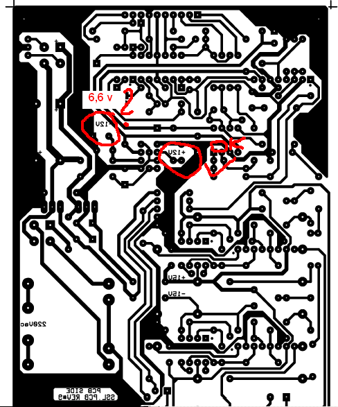
I have problem with electricity on gssl pcb board in this point it is + 6,6v instead of +12v !
Project not hase non side chain or of analogous supplementals, just classic compressor

any idea :?: :?: :?: :cry:

thx


ixi_error_ssl.jpg
 

Latest posts

Back
Top