GSSL HELP THREAD!!!

GroupDIY Audio Forum

Help Support GroupDIY Audio Forum:

This site may earn a commission from merchant affiliate links, including eBay, Amazon, and others.
Hello!

I'm S-L-O-W-L-Y putting together my first build: GSSL.

I wonder if a physical contact between the 1000uF caps and the chassis top will short the circuit?

I'm using the Panasonic NHG series caps, body height 25mm. Furthermore I'm using 5mm spacers for the PCB. This results only 1-2mm gap between the caps and the top, and the top is aluminium, thin and very flexible. So if I push the top when the unit is on and there will be a contact...what happens...?

Should I glue a rubber sheet under the top?

Cheers,

Miska
 
Ok,

Thanks Greg! :thumb::thumb:

So, without inslulation, the capacitors touching the chassis top WOULD short the circuit....right or wrong?

Regards,

Miska
 
I haope this hasn't been covered, I gave up after searching 32 of the 126 pages......
My current SSL compressor build is working perfectly, except no meter activity. The meter tests good, and with the ground side disconnected I see a varying DC voltage on the + side of the meter feed tracking threshold. When the ground side is connected, the signal goes away. What should I be seeing on the scope at the meter? Any ideas?
 
I doubt you'll see anything useful on a scope. tt's 1mA FSD, so it deflects based on current flow i.e. fully defected at 1mA. In the words on Jakob, check and double check for a mis-wiring on the control board.
 
nielsk,

Can be two things: Make sure that your 2K meter resistor actually is 2K, not 2M or something. Make sure that your meter actually is 1mA fsd (try ohming it with diode-test on your voltmeter, that should be able to deflect it fully)

3nity, - we've covered this many many times..

Jakob E.
 
What is Dist. Null? I cannot find it on any datasheets.

"Think, figure out power draw... " yes, of course. But how does one calculate power draw with a chip circuit?

(This is my first experience with chips.)
 
I'm still stumped about the distortion I'm getting with short release. Here are scope images as I've followed the distortion through the circuit. It's still a mystery:

These readings are from CV input to the channel VCAs (R10 on my numbered schematic). Moving the make up gain higher moved the whole waveform(s) downward and off the screen. Moving release to longer settings made all waveforms flat. Scope settings: Volts .1, Time .2ms AC and DC triggering were same image. Input is 1k tone @-23.5dB. The 1ma meter showed about 2 dB compression at 1:2 ratio, 1dB compression at 1:4 ratio, .5dB compression at 1:10 ratio:

R10ratioL.jpg

Ratio at 1:2

R10ratioM.jpg

Ratio at 1:4

R10ratioR.jpg

Ratio at 1:10
 
These readings are from Point "C". The waveforms are more dramatically unsinusoidal, and the Make up gain had no effect. As before, changing the ratios changed the waveform(s) and moving the release setting to longer release made the waves flat.

Scope settings same as above. AC and DC triggering were very similar but not identical.

CratioL.jpg

Ratio 1:2

CratioM.jpg

Ratio 1:4

CratioR.jpg

Ratio 1:10
 
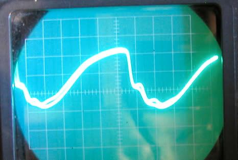
Interestingly, the waveform was not present at Pin 8 of THAT 2181 in the master sidechain VCA. Nor at Pin 6 of TL074. It was present at Pin 7 of TL074. These images below are from Pin 7 of the TL074.

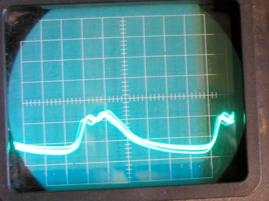
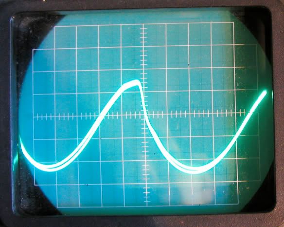
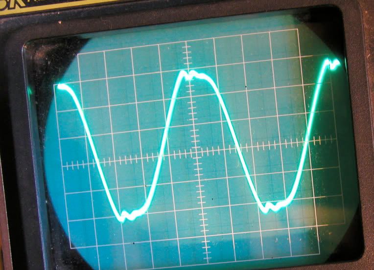
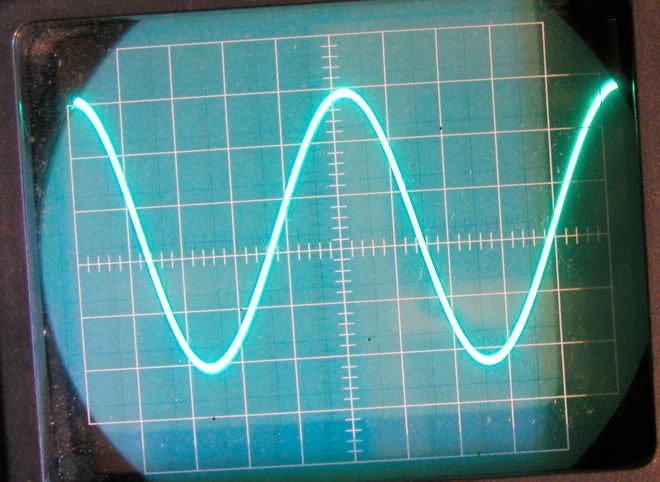
Does this mean the TLO74 is causing the distortion? This image is typical of my previous test sessions. I have seen it dramatically worse on the sine wave. Moving release to a longer setting clears up the sine wave.

Pin7RelsL.jpg

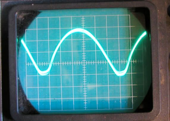
Ratio 1:10, short release.

Pin7RelsR.jpg

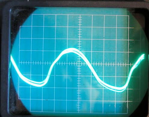
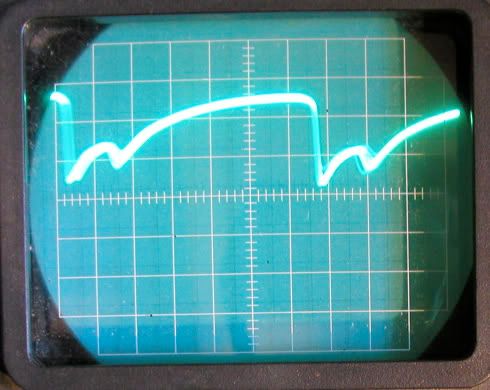
Same ratio, longer release.

Scope settings: Volts .05, Time .5ms. AC and DC triggering were the exact same wave.

So, I have many questions. What are we seeing here? What is normal? What is distortion? Why do the waves go flat at other test points with the longer release? Ultimately, where can this be coming from?

We previously hypothosized it was coming from the rectifier stage or the A/R circuit. However, if it is showing up at the first output of the TLo74, as in these images, that is before the rectifier and way before the A/R circuit. And it is not present at the master VCA output. Why is the release setting affecting the wave all the way back at Pin 7? I'm stumped.
 
I'm having some problems with my gssl again :(

It passes audio fine.

The bypass / makeup work

but there is no compression taking place. My threshold /ratio/ attack/ release/ all do nothing

there is also no sign of signal as my VU meter sits still while it passes audio

any ideas?

-richie
 
Crapsonny, Sounds like your sidechain is not getting signal, or not passing signal. Make sure your THAT vca is not backwards. Check the signal at the input of your sidechain THAT VCA on pin 1 and compare that to its output on pin 8. Look at the schematic and follow the path. Check the signal at the two 47k resistors which feed the sidechain. They should be feeding audio into the sidechain. Follow the path. Connection point "C" is a very handy test point as well. It should show negative DC when compression is taking place. Likewise at pins 8 on the TLo74 and pin 7 on the TLo72.

Look at the schematic. The two 47k resistors on the left are the start of the sidechain path, feeding the THAT chip. Follow the path until the final output where it says "CV to VCA's" and arrow up. Test along that path.

I've had a compression problem for 6 months and still trying to understand it. (See my posts above.) If you get DC readings or scope pix of your unit when it is working I would appreciate it if you could post them here, so I can have a baseline for comparison.
 
To make it easier to understand the puzzlement from my scope pix, I'll be specific:

1) Is it normal for the waveform to move downwards and off the scope when applying make up gain? Is this some kind of DC offset?

2) With longer release settings the waveforms went flat. Is flat correct?

3) Should the CV be a flat signal on the scope? If so, then what is the waveform? Is the waveform leakage of AC through the rectifier?

4) If the waveform is leaking AC, or audio, then why is there no waveform at the output of Pin 8 of the sidechain master VCA?

5) Why is the waveform not present at the input of the TL074 on Pin 6, but it IS present on the first output of the TL074 on Pin 7????!!!

6) Does this mean the TLO74 is causing the distortion? Or there is another source of this waveform than the natural output of the sidechain VCA?????

7) Why does the waveform go flat when I lengthen the release setting even at test point "C" upstream of the A/R circuit?????

8) Is it normal to see the audio signal on Pin 7 of the TLO74?

9) Why does the distortion in the sine wave, visible at TL074 Pin 7, go away when I lengthen the release setting? How can the release effect the signal so far backwards in the circuit?

10) It would be going backwards through the rectifier and several stages of the TL074, (which I thought would act as buffers)! Is this possible?

I think this troubleshooting could help everyone understand and troubleshoot the sidechain circuit.
 
thanks tommy

i'll be sure to post pics .. girlfriend is away for the week and has the camera .. i'll do those tests you suggested and let you know what i come up with .. maybe i'll help us both out :)

-richie
 
Back
Top