Hairball FET (1176 Style) compressor enclosure hints and tips

GroupDIY Audio Forum

Help Support GroupDIY Audio Forum:

This site may earn a commission from merchant affiliate links, including eBay, Amazon, and others.
I'd like to confirm 100% that everything is OK before excepting money, so I'll wait until I have them in hand before offering them.

I'll make the announcement in this thread when they arrive.

Thanks!

Mike
 
And when there is a stereo version, will it be set up for dials or switches?  Will it use the meters you sell?

Philo
 
baadc0de said:
Will there be a stereo version of the case available in the first batch?
I have added a link to Mike's own announcement in the first line of the first post. Please read his thread and ask questions about the case there. This thread was intended as a help thread for the cases.
 
Hi Guys,

The enclosures are up for sale.
http://www.groupdiy.com/index.php?topic=28923.msg454769#msg454769

Please post all purchase questions to that thread.  

This thread is for assembly hints/tips only

Along that line I wanted add that in addition to the assembly hardware, the enclosures are shipping with the screws, nuts and standoffs for mounting the PCB's, XLR, IEC and output transformer.

Thanks,

Mike
 
Here's my Rev A project almost complete, waiting on a few small parts to get her going.

UTC O-12, input, EA 5002 on the output.

Here's a few shots of the work in progress.

The beauty shot.

1176RevBuild-1.jpg


Some inside shots

1176RevBuild-2.jpg

1176RevBuild-3.jpg

1176RevBuild-4.jpg


Mike's enclosure is top notch, all the parts fit flawlessly, it's easy to work inside of and looks
killer when it's finished.

I'm waiting on some Neutrik D connectors, IEC connector, heatsinks, a 2K meter adjust pot, some 4/40 screws and a couple of 47uf/50v caps and she will live.

Soon...

Mark
 
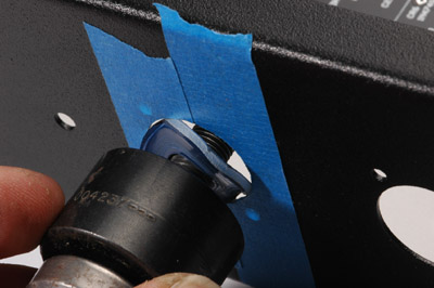
If you have a prototype case the holes for the XLRs are slightly too small to fit. But that's OK - pull out the Greenlee punch...but how to align it when you already have an almost-the-right-size hole there?

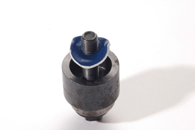
There's an alignment jig that gets left inside after each use:

greenlee_alignment_jig_forum.jpg


...looks like something left over from that Bloo I built almost a year ago.

Put it against the rear of the case as shown then screw on the punch from the inside of the case:

greenlee_alignment_forum.jpg


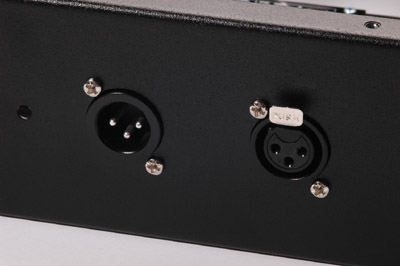
De-burr, use a little black Sharpie to tone down the bright metal and install the XLRs - good enough to rear mount the jacks:

hairball_rear_panel_xlr_forum.jpg
 
One thing I'd been thinking about is mounting the optional stereo link board.

Most people will probably use the side toroid mount to keep the power tx away from the output tx.  This will leave the rear toroid mounting hole available for your stereo link TRS connector (may need to be expanded).  For the switch, you can add a small hole to the front panel for a toggle, or eliminate the either the +4 or +8 pushbutton switch and replace it with a "link" switch.  For info on that see the part in the PCB documentation about adding the a bypass to that bank.  You download that on the switch PCB pages of the shop.

The PCB is pretty small and light.  You can mount one side of it to a rail and that should hold fine.

Thanks,

Mike
 
Damn - forgot to mention that only the prototype cases are affected with the too small XLR holes.

The cases sold on the Hairball site have the XLR hole size fixed.
 
A couple issues I've ran into:

The common alpha pot's for attack and release use a smaller mounting hole size. I used a #010 O-Ring on the back side of the panel to help hold in & center the pot. The O-Ring will hold the pot at center when adding the panel nuts and while tightening everything down. A slightly smaller and thinner o-ring should work as well and it should eventually sit inside the panels hole when the pot is mounted.

The other issue I've came across is the layout for mounting the input transformer don't take in account for the older (larger) input transformer PCB's. It's nothing a few well placed holes can't fix.This wouldn't be a issue if your buying everything now. I had bought my Iron about a year ago so I didn't receive the new pcb's that the cases is designed for.  

Lastly the meter hole is tight for a Sifam AL-29 bezel, the hairball bezel must be a little smaller. It just took a little effort to get it in there, luckily the sifam bezel is made of some heavy but flexible plastic.
 
A couple issues I've ran into:

The common alpha pot's for attack and release use a smaller mounting hole size. I used a #010 O-Ring on the back side of the panel to help hold in & center the pot. The O-Ring will hold the pot at center when adding the panel nuts and while tightening everything down. A slightly smaller and thinner o-ring should work as well and it should eventually sit inside the panels hole when the pot is mounted.

Ya the alpha pots have a 1/4" shaft and I designed the front panel for the more common 3/8" shaft.  I'm hoping to start stocking some pots down the road that will act as a better option to the Alpha's.  For those starting a new build, check out the Bournes output part on the BOM page of my site. It's 3/8" and is a higher quality pot, which is important for the output as it sits in the audio signal.

The other issue I've came across is the layout for mounting the input transformer don't take in account for the older (larger) input transformer PCB's. It's nothing a few well placed holes can't fix.This wouldn't be a issue if your buying everything now. I had bought my Iron about a year ago so I didn't receive the new pcb's that the cases is designed for.  

Thanks for pointing this out.  If someone has an old input PCB (uses links) and is ordering an enclosure just let me know in the notes when you order and I'll include a new PCB for free.

Thanks!

Mike
 
Will the case accommodate a Jensen JT-11 input transformer. I'm thinking of building a revision D using one and a UA-5002 output transformer.
 
sws2h said:
Will the case accommodate a Jensen JT-11 input transformer. I'm thinking of building a revision D using one and a UA-5002 output transformer.

There would certainly be space for it, but you'd have to drill a couple of mounting holes.

Thanks,

Mike
 
Hey Folks,
I am building my first MNATS/Hairball 1176F with components sourced from Mouser . I have a few minor questions and discrepancies I would like to identify to this group for comment:
1-The C1 capacitor is specified with a 5% tolerance in the BOM but the Mouser project list provided a 10% tolerance devise. Any potential problems issues?
2-Is it possible that the MNATS PCB designation for C2 and C5 have been interchanged?
3-R59 BOM value is 3.6Kohm and the MNATS PCB designation is 3.9Kohm. Which takes precedent? My choice was 3.6 based on the Schematic

I really appreciate the value of this forum and look forward to any input.
 
Hey Folks,
I am building my first MNATS/Hairball 1176F with components sourced from Mouser . I have a few minor questions and discrepancies I would like to identify to this group for comment:
1-The C1 capacitor is specified with a 5% tolerance in the BOM but the Mouser project list provided a 10% tolerance devise. Any potential problems issues?
2-Is it possible that the MNATS PCB designation for C2 and C5 have been interchanged?
3-R59 BOM value is 3.6Kohm and the MNATS PCB designation is 3.9Kohm. Which takes precedent? My choice was 3.6 based on the Schematic

I really appreciate the value of this forum and look forward to any input.

As your questions pertain to the Rev F project and not the Hairball enclosure I've answered them there.
 
reviving an old thread here for a question about the Hairball 1176 enclosure/kit.  I'm having a tough time sorting out exactly how the zero set 2k pot is supposed to be mounted on the front panel (doesn't seem possible to set the pot at a proper distance from the front panel hole).  Is there any trick to doing this using the provided hardware, or is it just a matter of going down to the hardware store and getting a handful of thin washers to tweak the spacing? 

anyone have a closeup picture of how theirs is mounted?  my enclosure is newer and has the longer (1/2"?) zero mount standoffs, so the information in mnats' first post in this thread doesn't really apply anymore.
 
Back
Top