Harrison 3232 console restoration

GroupDIY Audio Forum

Help Support GroupDIY Audio Forum:

This site may earn a commission from merchant affiliate links, including eBay, Amazon, and others.

timkroeger

Member
Joined
Oct 27, 2011
Messages
11
Location
Germany
Hey everyone,

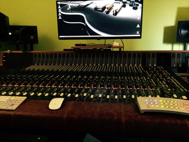
I'm currently restoring a Harrison 3232 that I bought from a nice guy in Hamburg for my control room. It's currently loaded with 25 channels and seems to be in pretty good shape. Recapped some time ago and only a small burnt area in the vicinity of the phantom power switch. Someone modded that section and upon removal seems to have connected the wrong leads...

Anyway all channels except channel #6 pass audio coming from multitrack A return and feed the 36 segment :) meters in Return Mon and Return Mix mode. A quick FET card and channel strip swap with #6 confirmed that the issue lies with the I/O board and FET and edge connectors are fine. We'll see. I thought I'll post some pictures and document what I'm doing and have already done; and maybe if I get stuck somewhere, someone here can hopefully help me out. I've learned a lot from previous Harrison posts already (Frank!!!) and studied the manual/schematics three times by now - I think. It's still a little alien to me though ;)

console.jpg


Since I'm missing a few channels I was searching around and found someone who offers channels from an early 4032 but he claims that they are running on +/-24V for increased headroom. No mod, just very early 4032. I've seen PSUs with warning lights for only +/-15V and +/-24V but my PSU features +/-15V, +/-18V and -24V. From the docementation I learned that a lot of the logic seems to rely on the -18V / -24V difference so I'm curious: do you know of these earlier models or is this a misunderstanding?
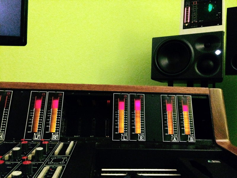
signal.jpg


It would be awesome to increase the number of channels since I have a lot of outboard and want to hook up an Orion 32 for the digital stuff and my Studer A80 for analog.

So what did I do already:
  • Had the right stand patched up - new bolt replacing a broken nut
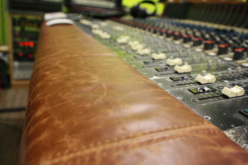
  • New leather for the armrest
  • Sanded and repainted the wooden sides
  • Fixed PSU hookup which got damaged during transport
  • Fixed some meter cabling
  • Measured PSU, slowly brought up the console channel by channel
  • Replaced a few 74C157 with CD40257BE as suggested here by Martin B. Kantola in 2009 to rule out some strange behaviour

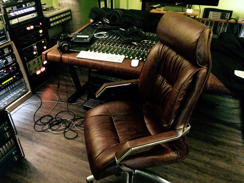
studio.jpg


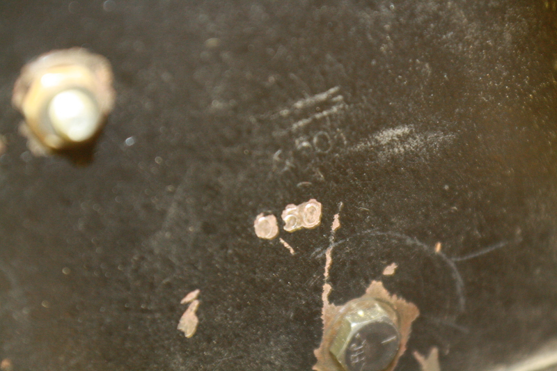
I found a number stenciled into the inside of the right flange which reads 050; is that the serial number or is it to be found elsewhere? It has the black dbx 202 cans so A model it is?

I'll post some more pictures and probably some closeups of the strips later!

Cheers
Tim
 
So I've had some time to take a few pictures.

New armrest:

harrison-new-armrest.jpg


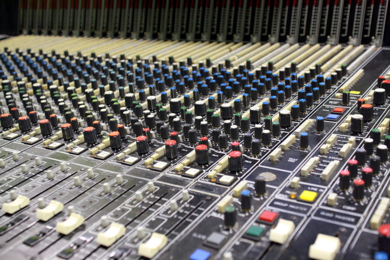
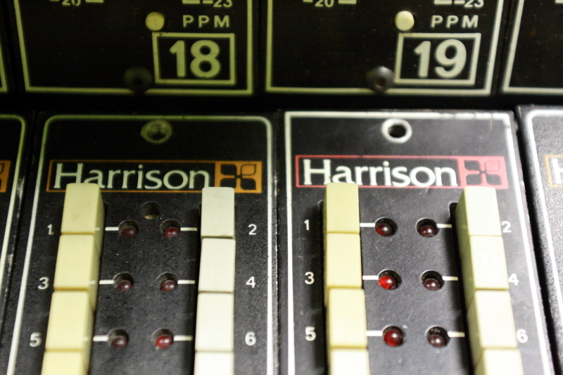
Channelstrips:

channelstrips1.jpg


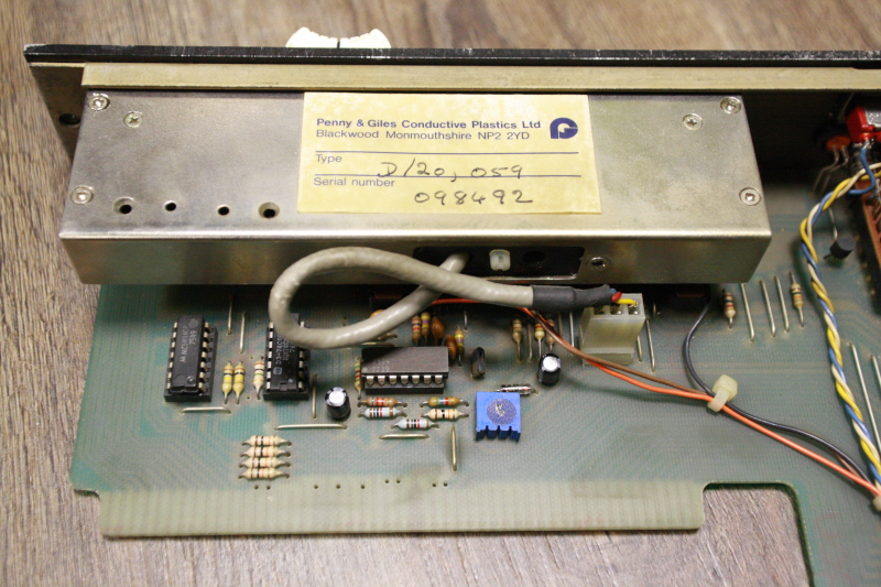
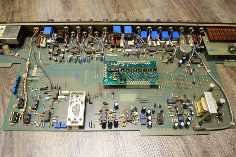
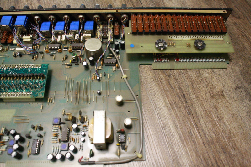
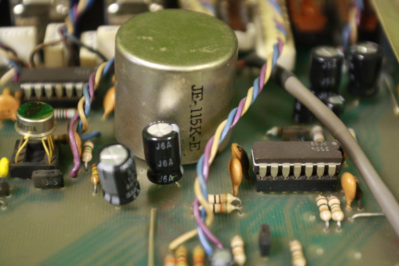
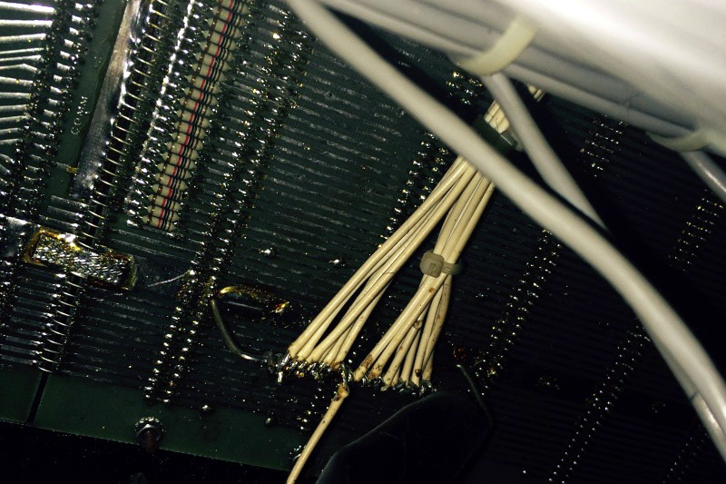
Channelstrip component side:

channel-strip-component-side1.jpg

channel-strip-component-side2.jpg

channel-strip-component-side3.jpg


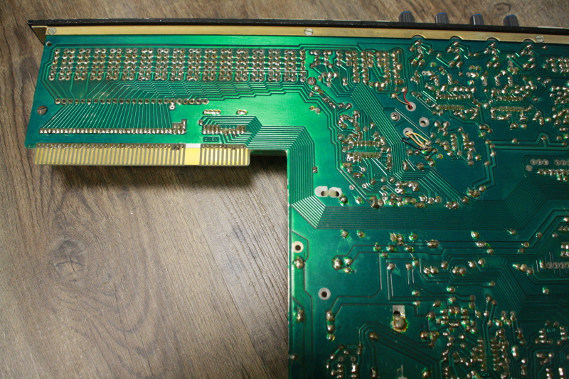
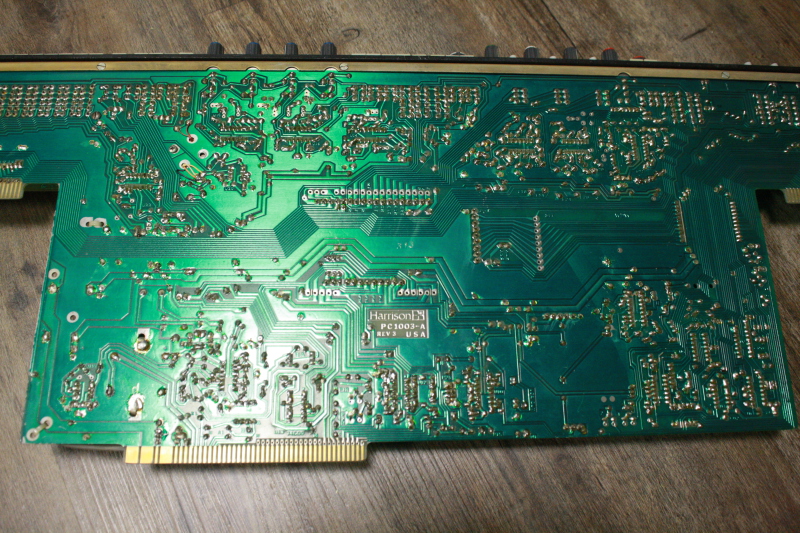
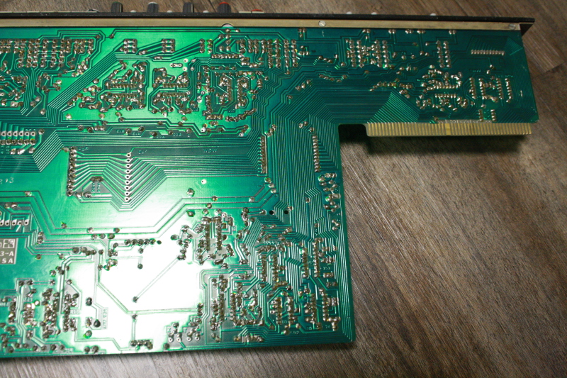
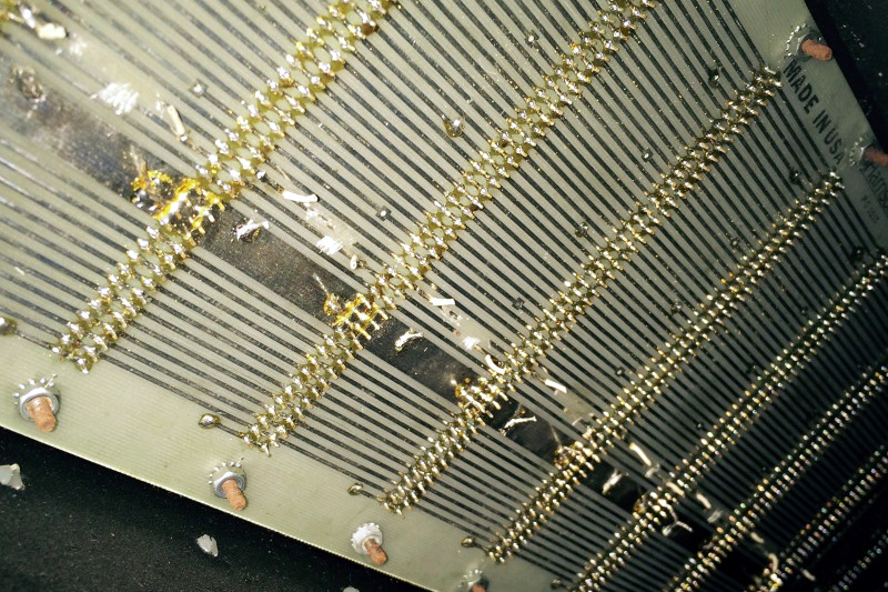
Channelstrip track side:

channel-strip-track-side1.jpg

channel-strip-track-side2.jpg

channel-strip-track-side3.jpg


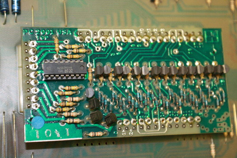
FET

channel-strip-fet-board.jpg


Iron

channel-strip-iron.jpg


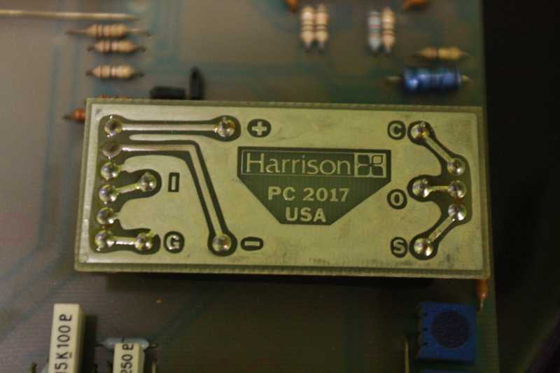
VCA

channel-strip-vca-board1.jpg


One channelstrip has different colors (left: normal, right: odd one)

top-lettering.jpg


Serial number?

serial-number.jpg


Also what looks like a star ground mod:

motherboard3.jpg


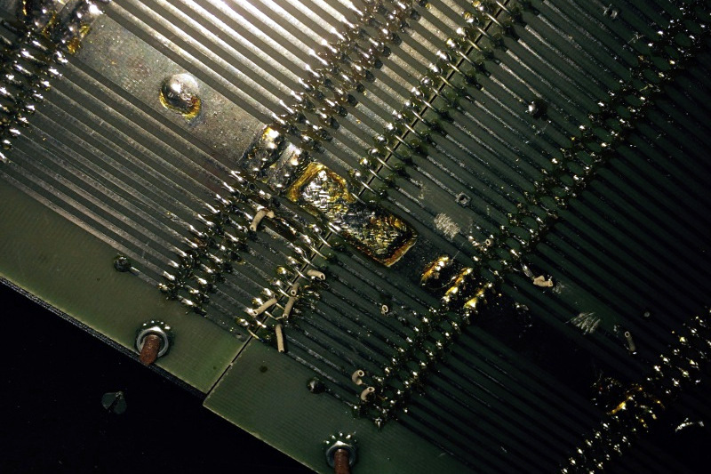
...and some strange modification that seems to have been ripped out again:

motherboard1.jpg

motherboard2.jpg


I wonder what has been done there...

Cheers
Tim
 
Wow!

That look sooo good! What is that FET card doing? Im only familiar with the MR3 and the only cards there are for the EQs. Is this console also using a lot of logic switching?

It took me like 3 months to figure out how to rack my MR3 strip☺
 
Hey synthiaks,

the FET cards do the logic switching and signal routing for the different operational modes (tracking, mixing...) and provides functionality like mute all - one for each channel. I'm currently learning the different modes and experimenting with signal flow; the manual has very good diagrams to explain it. While the manual is quite pricey, I'm glad that I ordered it from Harrison as it is a really, really nice and complete package. They are unbelievably helpful there: had to create a hardcopy of it and put it together by hand. It also includes a lot of the update/upgrade/support memos and modifications regarding VCAs for example. They were really fast, too!

Best regards
Tim
 
Hi Tim,

OK that's cool so they did all the routing with FETs on the earlier consoles? Why did they put them on a single card? The signal traces must be crazy around that card. As far as I see you have Transformer balanced inputs.

On the MR3 it is analog switch ICs. I only had a strip so the different mix modes on the master module of the MR3 I had to figure in the blind. I came to the conclution that it had a fader swap mode, A/ B mode and line/mic input modes. I still haven't used a whole MR3 though!

Nice with the manual. Do you have valley people VCAs?
 
No, just the black can dbx 202 VCAs.  I have two gold can VCAs on the workbench but I won't try anything with them until I went through the whole board.

I've attached an oberview of the FET card's pinout. It has some sends and returns, yes ;)

Best regards
Tim
 

Attachments

  • image.jpg
    image.jpg
    281.3 KB
Oh man...

I wonder why they didn‘t sprinkle them over the PCB, SSL style. Were the FETs prone to break?  Some Traces must travel a much longer way there than they should have to... But the card and pinout gives you a nice overview of all the patch points.

But who am i to complain? My MR3 strip sounds fantastic so i guess this must be an Absolut dream of a Console, With or without long traces!


timkroeger said:
Since I'm missing a few channels I was searching around and found someone who offers channels from an early 4032 but he claims that they are running on +/-24V for increased headroom. No mod, just very early 4032. I've seen PSUs with warning lights for only +/-15V and +/-24V but my PSU features +/-15V, +/-18V and -24V. From the docementation I learned that a lot of the logic seems to rely on the -18V / -24V difference so I'm curious: do you know of these earlier models or is this a misunderstanding?

A version (yours is B or C) uses only +/-24V PS and makes +/-18V locally using 7X18 regs. As I know, A version modules cannot be used in your console without modifications. There is one nice A version 4032 console in Hamburg area. :)
 
That's interesting info, moamps. Thank you so much!

It should be much easier to do the 24-to-18V conversion on an A module than to do the different mod on a B or C module right? I don't have a lot of experience with VCA circuits and their alignment, yet but I think basically stripping the A boards of their regulators / bypassing them and fetching -24V from the corresponding connector should be enough to get them going. Probably need to be careful and see where exactly -24V is needed and where the circuit needs a few cuts to feed it the -24V. Do you or someone else have the schematics of the A version I/O module and a pinout of the edge connectors so I can make up my mind if I want to go down that road?
 
Hi,
here is the not so good picture of the input module schematic. That's all what I have in an electronic form.
I believe it's enough for getting the picture what should be changed. If you need any other information please PM me.
Regards
 

Attachments

  • harrison_input_sch.JPG
    harrison_input_sch.JPG
    731.6 KB
Hey all,

been busy building rest of the studio, bringing the 3232 up and also fixing the multitrack and some outboard. Thanks again, moamps for posting the Rev A schematics. After digging into it, I finally abandoned the idea of a quick A->B/C conversion; I'm still in the market for an additional 8 channels of B or C revision.

Now, what I have been working on regarding the 3232:

  • Some emitter resistors (10R) of output line driver burnt -> swapped
  • Some .01 bypass caps burnt at mic input, shorted, drove the phantom source to burn -> fixed
  • Resoldered some of the FET cards pins and cleaned them to cure some low levels and erratic routing behavior
  • Resoldered and swapped some switches that weren't working. Mostly solo switches.
  • Fixed a few broken connections at the patchbay. Cables probably got exercised too much on transport.
  • Replaced a few quad opamps (3504) where they had gone bad.

Because I had to swap some bad opamps and 3504 aren't available I experimented with MC33079, OPA4227 and LME49740 in the master section so that the path to control room exclusively features modern opamps. To be honest I didn't hear a difference between those three mentioned above; what I noticed though, is that replacing the old 3504 opamps kind of lifted a blanket. I have a lake people converter hooked up to one tape return and have the consoles control room outputs and the converter's ouputs additionally hooked up to an external monitor/source switch, so I can compare both carefully level matched signals (original and through the console). After replacing the opamps I can hardly hear a difference between the two where before the soundstage sounded a little dull and constricted. Bass is still a little better defined when going direct. Ishould find out how to measure and compare. For every opamp spot I picked the type that stayed cooler. I still need to figure out how to probe effectively for HF oscillation and will post my findings.

So far I have all 24 channels performing nicely with the master section. The only thing still bugging me is in the dim logic, that can't be turned on via dim switch, only turning off works by pressing dim after turning on e.g. via slate.

Cheers
Tim
 
The above schematics are A schematics. It's a simple 1:2 judging from the B & C schematics where it is indeed printed. Nothing fancy for the output stage. You only find Jensen at the input stage as far as I know.


Attachments

  • IMG_3519JPG-1.jpg
    IMG_3519JPG-1.jpg
    1.1 MB
OK I read this output transfo is poor quality...
On the input it is a Jensen 115k on A version then a Lundahl. I guess a 1:10 too... Probably a LL1578
 
Yes, on the input it's a JE 115K. I don't understand what you're saying in regards to Lundahl though. As far as I know the transformers didn't change between the revisions but there are transformerless versions. Not sure I'd label the output transformer poor quality though, it's not boutique but I'm sure it was carefully chosen at the time ;) Also it's "just" a line driver.
 
I remember that it was in the Harrison 32CS new channel strip they put the Lundahl in the input.

http://www.harrisonconsoles.com/site/32cs.html

In the clone I am designing I will put an IC line driver (transformerless)
 
Hello guys.
waking up an old thread here.
I am fairly new to the harrison 3232 consoles. And I have a story to tell.
in 2015 I was strolling through a weekly flea market in my city. This particular flea market met weekly for a few hours in a parking lot behind a gas station in the old part of town. It usually features various trash pickers from around the city, they turned up to sell their weekly finds. It's usually used pharma supply, old silver and bronze ware, half used bottle of imported shampoo, etc. You know, the stuff that trash pickers tends to turn up. Once a while I find microphones, surplus switches, and pots there.
On this particular day, one of the trash electronics guy saw me, and said that there's a piece he kept for me. He gestured to a somewhat beat up piece on his tarp. I looked at it. It's a channel strip. It has the Harrison logo on it. I didn't know what model it came from. We haggled. We agreed on a price, I bought a channel strip. Then, as I was about to walk away, the guy called out to me and said:"you know, I still got a stack of these in my warehouse if you are interested. " so that night, I drove out to the guy's warehouse, and bought myself 20+ channel strips from the guy's warehouse.
I wrote to Harrison that night, telling them the channels I found, sending a picture along.
I got a reply the next day. I was told that I found a a bunch of 3232c channels. some of them were input channels, some were master section channels, monitors etc. Out of the blue, at a flea market from a trash picker, I bought myself a half a 3232c console.
So, from 2015 and on, I have been slowly restoring the channels, doing a little whenever I have time, Replacing caps, etc. As I go along working on them, the fact that the console had been in the world for 40 years became obvious. the copper on the pcb were partially peeling. So.... to rectify that, I decided I was going to have new channel pcbs made. I was 16 some channels away from a complete console anyway, may as well go head and bite the bullet and make them. So I went that route. I made new channel pcbs.
But... these stuff were designed during the 70s. As I was building the first channel, the fact that a single layer pcb meant patch wires like the original was annoyingly unnecessary in today's standard. The fact that on the component side there's no notation whatsoever made the process somewhat slow. So... I was thinking: "hell, I already made the pcb. may as well edit the pcb file and make it a dual layer pcb, draw in the patch wires, and do a overlay on the component side and write all the notation on there.
So I went that route.
And I am still on that route. I am about to finish with the main channel pcbs. The channels I am working off of are 3232C. the version with transformerless mic amps cards and allison research VCAs. The only schematics I found a few years back were the ones with a jensen input transformer and 202 VCA. Not sure which version this one is. Going through component by component the dbx version and the C version I got are 90% similar with 10% difference.
So here are my 2 questions.
Does anyone has the channel schematics for 3232C console with transformerless mic amp cards and allison VCAs?
For the folks with the dbx 202 VCA and the jensen input transformer, can you show me a picture of the component side around U9?
Thanks in advance to all you fine folks out there.
 
I unfortunately don't have whole channel schematic but have  schematics for transformerless mic preamp and Allison VCA what may be helpful for you. 
 

Attachments

  • harrison mic preamp allison vca.pdf
    145.1 KB
abbey road d enfer said:
So you're re-designing a product based on LM394 and EGC101, both obsolete...?
well, no, not really. To reconsider routing and redraw a fresh board is one thing, to have a old stripped board scanned and imported into a pcb file for editing is significantly simpler. The intention is to be able to resurrect the peeling channel strips that I have, while making building new channels easier. I haven't decided if I will keep using the old bits. should I choose not to, modifying it would be like modifying a original channel pcb. If I fuck up somehow, I will have fresh spare pcbs to work with.
 

Latest posts

Back
Top