HE-569 pre/eq 500 series

GroupDIY Audio Forum

Help Support GroupDIY Audio Forum:

This site may earn a commission from merchant affiliate links, including eBay, Amazon, and others.
I've just sent pub ver 2 to the manufacturer, should be here in few days, then I have to build and test the unit... lot of work for this baby
 
Nice work Paulo  :)
I like that you've made the amplifier boards as daughter cards for ease of switching, fixing, building etc.  but not constrained yourself to the usual 990 footprint and sizing enabling you to get more stuff on the cards.
Did you come up with your own format in terms of pin locations etc?  Or is there a standard other than 990/2520? 
I'm working on a similarly sized amp board but can't seem to decide on a standard to stick to.
Anyway, looking good so far fella 👌
 
Winston O'Boogie said:
Nice work Paulo  :)
I like that you've made the amplifier boards as daughter cards for ease of switching, fixing, building etc.  but not constrained yourself to the usual 990 footprint and sizing enabling you to get more stuff on the cards.
Did you come up with your own format in terms of pin locations etc?  Or is there a standard other than 990/2520? 
I'm working on a similarly sized amp board but can't seem to decide on a standard to stick to.
Anyway, looking good so far fella 👌

Thank you John,
The format is an idea of mine, nothing really special.
the idea behind the boards is to have the capability to insert them vertically like a 990/2520 footprint but also horizontally into a connector with a 2.54 mm pin space. So if someone is going to use them in a more point to point build like the original modules he has the ability to do it.
it is also practical so i can insert them in a breadboard to run test for them.
Great to read Paolo. I'm so excited to see this as your work thus far has been very remarkable.

thank you Rocinante!
 
pahstah said:
Thank you John,
The format is an idea of mine, nothing really special.
the idea behind the boards is to have the capability to insert them vertically like a 990/2520 footprint but also horizontally into a connector with a 2.54 mm pin space. So if someone is going to use them in a more point to point build like the original modules he has the ability to do it.
it is also practical so i can insert them in a breadboard to run test for them.

Great, I like it!  You gave me the push I needed/wanted to just go ahead and do something similar.  Thanks Paulo. 
Marking this thread so's to keep up to date on it 👍
 
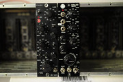
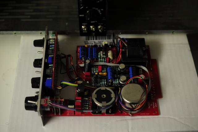
this the second version, with the frontpanel design. there's stillsome adjustment tommake so i will do a thrid version that hope will be the definitive one. the main problem is oscillation above 70 db of gain with the 1:10 tap inserted, no oscilation with the 1:1 tap.


DSC0011.jpg


DSC0012.jpg
 
pahstah said:
the main problem is oscillation above 70 db of gain with the 1:10 tap inserted, no oscilation with the 1:1 tap.

Can you determine where the oscillation is as regards frequency and particular transistor?

Just in case you haven't tried this, an easy trick in keeping a particular transistor from oscillating is to put a lossy component in two of its three leads.  Either small value resistors or ferrite beads right at the transistor.

 
Just chipping in to agree with others above - this looks grand, and I really like your v2 faceplate. I find it easier to parse than the 500-series Helios, somehow.

I’m curious as to which direction you went on the gain control in the end - did you use a two gang switch to expand the headroom, or something else? Edit: Just noticed the “Boost” button, is that the trick?

I also note a screw hole in the bottom right corner of the main PCB, are you considering an L-bracket to strengthen the module? With that much iron on it, I guess it may need it!

Great work. Can’t wait to see the finished product.

Andy
 

Latest posts

Back
Top