Success! Figured I'd just put the build report in this thread:
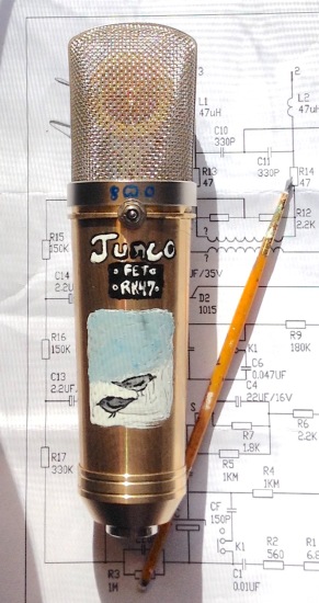
This is my build of Aurycle's FET mic kit, my first from-scratch mic kit build. (The others were projects I picked up partially finished or modded existing mics.)
We had lots of snow birds (Dark Eyed Junco in their winter plumage) outside the window this morning. So it got named after them. It's also a bit of a pun on the mic quality.

The body in these kits is actually really nice heavy brass (especially for the low price), way nicer than the Alctron bodies (except you have to finish it yourself) and nicer than any of the cheap Chinese gut-ables that I'm aware of. It came with a 32-mm 67-style capsule that was decent. The stock transformer is at least passable and some people have said that they think it's good and doesn't need replacement.
The kit has some questionable components and choices, though:
1. The 2k2 power splitter resistors (the ones on the transformer secondary) were pretty far from matched. I just did the sensible thing and matched them to the ohm from my parts bin. I also matched the 47R on the output.
2. There were tantalum and ceramic caps in the signal path. I replaced the ones that mattered. The tants left are just filter caps. I should probably replace them with electros to be safe, but it wasn't critical to me as they do their job there (low ESR) and I don't really want to lift more pads going back in to replace them.
3. The FET bias is fixed (and would have been quite incorrect for the supplied FET). I ended up using a 2SK30 to get a little more signal swing (the gain isn't maxed out anyway) and because I thought it sounded a little crisper after trying both (though admittedly unscientifically). I put a trimpot in place of the 1k8 with bypass cap in parallel so it didn't affect the gain to adjust the bias and ended up at 11.3V. Note that some people trim the other source resistor (the 2k2) -- in my opinion, that's a worse process because it changes the gain of the circuit when you trim it.
4. The slide switches that came in the kit were really lousy. I can't say that the larger toggles I used were a great idea ... I had to file out the bottom of the slots to make them fit. If anyone knows any really tiny toggles or nicer slide switches, I'm all ears! Adding the pattern switch was my main goal for this adventure. I'll talk about that below.
5. The high-pass filter was a bit more extreme than advertised. It said 100Hz, but it was actually 130Hz, and the "full range" mode's cutoff was 15Hz, which I think is a bit high. Since I was replacing the toggle anyway, I put in a 3-way and made it 130Hz/70Hz/4Hz, replacing the largest cap with a 1uF film cap (fit easily) and upping the 180K base resistor that followed to 220Hz. Since I was improving the low-end throughout, I went ahead and made the 4.7uF tantalum output capacitor a film ... uhhh mess of caps. There are six of them in parallel (three are on the rear of the PCB). I added a uF to the total to be sure that the transformer's primary inductance didn't cut some low end. Yes, I should have used a single film cap. I didn't have it. Can't see it from the outside!
6. Worst mistake in the kit is that they left some parts that do nothing but add noise. There's a 6.8K and 560R in series with a 10nF cap to ground from the backplate in the schematic. In the 87 schematic, this is a test signal input but they serve no purpose here. (There's a thread somewhere on this board that mentioned this, but I'm not sure which post it was.) I didn't realize that I forgot to leave these out when I first buttoned it up, and realized when listening back to the omni recording that the noise was much higher than expected. (You can hear this on the demo recordings when I finish uploading them.) When I removed them it dropped the noise considerably. The noise difference is minimal in Cardiod (must be only a decibel or two, if at all) but it's at least 6dB in omni! The self-noise in omni is a little better than my D251 build but actually not quite as good as the line audio OM1, which is surprising.
7. The pad switch is actually somewhere between -6 and -10dB depending on the pattern. I can't measure it perfectly, but in cardiod it's definitely only ~-6dB. Since that is the stock pattern, I am slightly annoyed that they printed "-10dB" on the mic body! I'm not totally sure but I think 250pF is the correct value for -10dB. Maybe I should have tried a three-way switch there, but I rarely use a pad anyway.
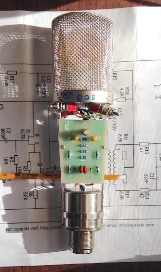
I replaced the bits that needed replacing, did the hi-Z section "dead bug" style, and used an RK47 capsule so I could add a simple pattern switch. The capsule from this kit went in the modded 990 that previously housed the RK47, and it sounds pretty good there -- the low end in that mic is the biggest of the three I think. It just didn't have a rear membrane, so it couldn't do patterns.
Some miscellaneous other mods and part upgrades along the way: film caps in the signal path, silver mica for the pad cap (this might have been better as a straight film cap, I think film has lower leakage, but we're talking hundreds of megaOhms here either way, so I thought it was a safe). I was using an RK47, so I lowered the deemphasis caps to 100pF. Why didn't I remove them completely, since the capsule doesn't need them? I figured it rejected RF at best and did no harm at worst. I probably could have left them 330pF. The 330pF look to me to be pointless here because the other side of the transformer is a source follower. They don't reject anything in the audio range based on what I'm calculating.
This build didn't go off without a hitch. The PCB pads lift easily because they aren't through-plated (single-sided printed circuit board, how annoying!), so adding the mods created some havoc.
I also had probably the weirdest, and most insanity-inducing issue I've ever had in any build of anything, and it took me almost 12 hours to verify and finally fix: The mic would stop working if I held it face-down. But I could make it come back on if I squeezed the top of the basket. I hammered the top edges gently with the butt of a screwdriver and the problem disappeared completely (I can't even make it reappear now). So the solution was every bit as nonsensical as the problem. I must have torn the thing apart 50 times, checked every component, replaced every suspect part, and did continuity and voltage checks on every part including every inch of the body and headbasket. Drove me absolutely insane.
Okay, about those patterns. Updated schematic:
In cardiod, the rear membrane is held at ground by a 100M resistor. When you switch to connect 1 and 2, it connects the rear membrane to the filtered polarization voltage (about 40V in this mic, because there's a source follower drawing some current) through a 330K resistor, putting it in phase with the front membrane -- omni mode! When switched to the center, it's dropped back to ground, putting it in phase with the backplate, and we're in cardiod. When switched to figure 8, the backplate is dropped back to 0V, while the 1G resistor on the backplate is now connected to a node at half supply, putting the rear membrane out of phase with the front membrane and the backplate halfway between them -- producing a figure 8. Nifty, eh?
You'll notice this involves using the backplate as your output voltage, instead of the front membrane the kit has.
One drawback to this is that the polarization voltage drops by half in figure 8. I don't find this to be hugely problematic in my case, but for people looking to squeeze every bit of gain out of the circuit ... maybe just do the omni mode (which just shorts the capsule membranes and doesn't require any extra resistors).
I basically just decided to record my practice this afternoon, so I have a ton of test recordings, which I can upload. They'll be MP3s. Here's the links:
Cardiod:
-Junco RK47: https://dl.dropboxusercontent.com/u/9878279/Test%20recordings/Mic%20Test%20-%20Junco%20RK47%20Cardiod%20012416.mp3
-D251 (tube mic): https://dl.dropboxusercontent.com/u/9878279/Test%20recordings/Mic%20Test%20-%20D251%20Cardiod%20012416.mp3
-MXL 990 modded with film caps and using the capsule that came with the Aurycle kit: https://dl.dropboxusercontent.com/u/9878279/Test%20recordings/Mic%20Test%20-%20990-67%20Cardiod%20012416.mp3
Song list:
Recording chain in all cases was: D251 through the Fireface's preamp; MXL, Junco, and OM1 through Baby Animal Neutrals. I didn't want any preamp color. No post processing on anything. I'm recording in our library, so it's a smaller room than where I normally record, and it's pretty dry in here. (There is a weird high-pitched ringing sound in one corner I'm trying track down ...) The tracks are normalized, and I adjusted the gain of each. The Junco has the least output of all of these, so I'd consider it on the low side for a condenser.
Song list:
Take This Hammer (Leadbelly)
Little Sadie
Cindy
Dark as a Dungeon
Go Down Hannah (Leadbelly)
One More Dollar (Gillian Welch)
Omni:
-Junco RK47: https://dl.dropboxusercontent.com/u/9878279/Test%20recordings/Mic%20Test%20-%20Junco%20RK47%20Omni%20012416.mp3
-D251: https://dl.dropboxusercontent.com/u/9878279/Test%20recordings/Mic%20Test%20-%20D251%20%20Omni%20012416.mp3
-OM1: https://dl.dropboxusercontent.com/u/9878279/Test%20recordings/Mic%20Test%20-%20OM1%20%20Omni%20012416.mp3
Song list:
I Ain't Got No Home (Guthrie)
1952 Vincent Black Lightning
Georgia On My Mind
You Don't Know Me
Bridge Over Troubled Water (Simon and Garfunkel)
Four Winds (Bright Eyes)
Pretty excited to move onto the next build.
Oh, and I took measurements of the PCB and made a template. I'm strongly spending the extra money on PCBs from OshPark for my next build so I don't have to worry about more PCB failures.


![Soldering Iron Kit, 120W LED Digital Advanced Solder Iron Soldering Gun kit, 110V Welding Tools, Smart Temperature Control [356℉-932℉], Extra 5pcs Tips, Auto Sleep, Temp Calibration, Orange](https://m.media-amazon.com/images/I/51sFKu9SdeL._SL500_.jpg)