sonolink
Well-known member
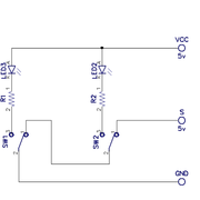
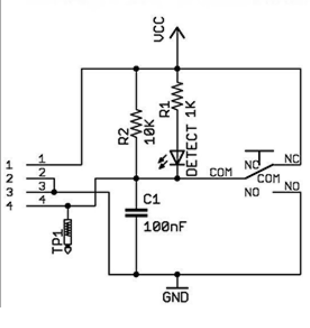
I bought these 3 pin Makerbot type endstops that have an LED for my new CNC and would like to confirm that the wiring to use 2 switches per axis in series Normally Closed is as follows:
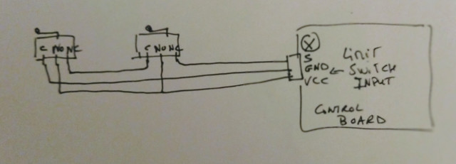
NC triggers the Alarm and NO lights up the LED. Could someone please confirm it's correct?
Cheers
Sono
NC triggers the Alarm and NO lights up the LED. Could someone please confirm it's correct?
Cheers
Sono
")