Help with Mackie Big Knob Repair

GroupDIY Audio Forum

Help Support GroupDIY Audio Forum:

This site may earn a commission from merchant affiliate links, including eBay, Amazon, and others.

sonolink

Well-known member
Joined
Feb 15, 2010
Messages
1,373
Location
London-Madrid
Hello,

I had this Mackie Big Knob in the cupboard for a couple of years. I used it in the studio for about a year before putting it away and it worked fine all the time. I was about to give it to a friend that is opening a small studio since I don't use it anymore and surprise! it won't power up. No LEDs at all.... :(

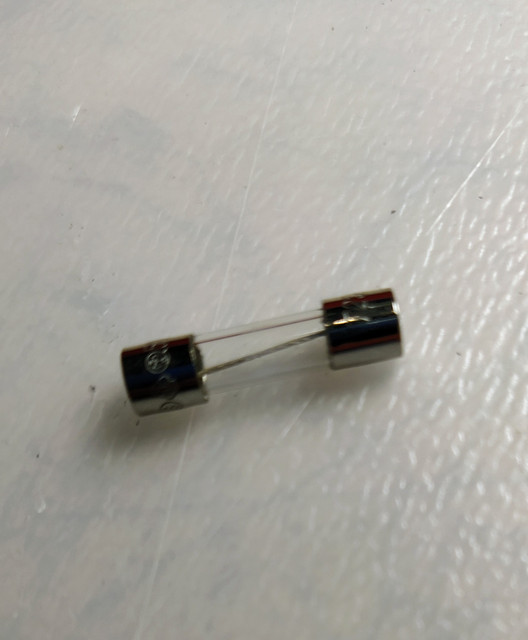
So I opened it up and checked the fuses. Visually they look ok but one won't check continuity.
According to the schem here
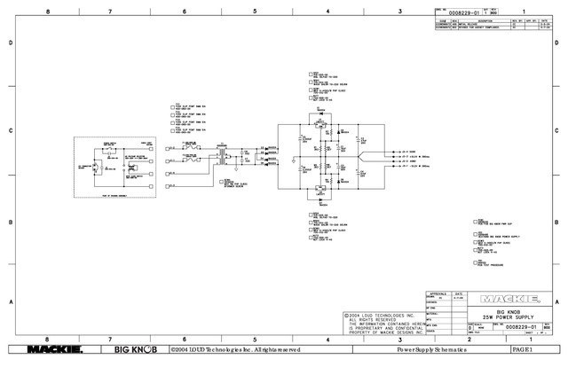
there is a fuse for each transformer winding. Could it be that one winding is shorted or would the problem come from elsewhere?
Fuses required are 250mA. The closest I have is 800mA. Is it safe to take out the PSU, and check voltages with a 1A fuse or I should go get a 250mA to do that? Or is it obvious that the trafo is dead and I should just order a replacement?

All your advice is as usual very much appreciated :)
Thanks
Sono
 
I wouldn't put a bigger fuse in there. If anything, I would put a lower fuse in for diagnostic purposes. That think probably only uses 100mA. Maybe less with all of the switches set for most LEDs to be off.

Then of course you can dig deeper with a meter. Even without a fuse you should be able to check the transformer windings for sane and consistent readings.
 
squarewave said:
Then of course you can dig deeper with a meter. Even without a fuse you should be able to check the transformer windings for sane and consistent readings.

How would you do that? Please explain :)

Cheers
Sono
 
sonolink said:
How would you do that? Please explain :)
Just measure the resistance of each winding. If any are short or open, that's obviously not good. They should be lowish like maybe 10 ohms or some such. Each of the primaries should be the same and each of the secondaries should be the same.
 
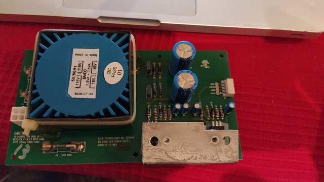
This is the Power supply board:


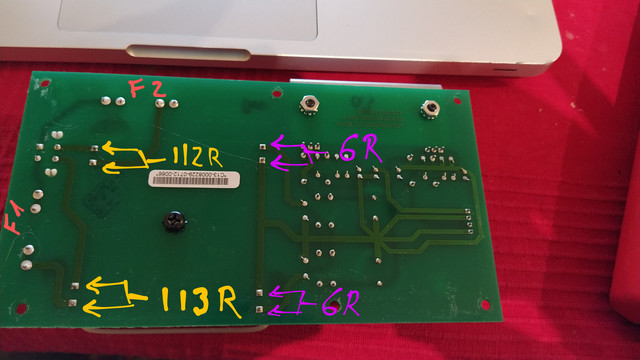
And these are my readings:


Transformer seems ok, right? If so, what could be te problem apart from the blown fuse? I am taking as a premise that the fuse was blown by something going wrong on the board but the fuse looks ok visually although it reads OL when measuring it's resistance... ??? Maybe it was a dodgy fuse?


I should probably get a proper fuse tomorrow and switch the power board on and check voltages? What if it blows the fuse? Where do you think I should head to? Thanks a lot for your help ;)

Cheers
Sono
 
Yeah, it looks fine. Just pop in a new fuse and see what happens. If it starts smoking and then bursts into flames, that means there's something wrong.
 
I would suspect (one of) the capacitors across the secundary winding, or (one of) the 2200 uF buffer capacitors.
(Or maybe one of the diodes in the bridge rectifier, not very likely.)
 
I just bought the fuses and the caps. I'll replace everything if the fuse blows and report back

Thanks a lot for the help ;)
Cheers
Sono
 
Something else is happening. I replaced the 4 caps and switched it on. The LEDs lit up for 1-2 secs and it went dead again...

Any ideas?
Thanks
Sono
 
Did you test the power supply without any load?

If the fuse doesn't blow without the rest of the electronics connected, something on the main PCB is causing a short circuit.

You could measure the resistance of the +15 and -15 volts input (to ground) of the main PCB.
So: on the connector that normally connects to the power supply.
Try to do measurements both ways, reversing the wires of the meter. This will reverse the polarity.
 
Ok. Well at least you narrowed it down to one half of the power supply. That's pretty good progress. There aren't that many parts. And you've already eliminated the filter cals. Which fuse blows? The positive half or the negative half?

You might be able to check the diodes with a meter. Measure they're resistance. If one is shorted, that's not correct. Does your meter have a diode voltage measuring mode? It might not be accurate measuring them in the circuit but if one is inconsistent, that would be a clue. Next would be to replace that voltage reg maybe.

Just keep going. You're getting close now ...
 
RuudNL said:
I would suspect (one of) the capacitors across the secundary winding, or (one of) the 2200 uF buffer capacitors.
(Or maybe one of the diodes in the bridge rectifier, not very likely.)
+1

Of course first step is to replace the fuse with proper value, sometimes they just fail.. If the fuse opens again keep looking.

More likely fault is PS reservoir cap, or shorted diode.

Sometimes after sitting idle the large electrolytic caps need to formed in again. The first application of power may have been enough to reform them and a new fuse will work the second time.

All speculation of course.

JR
 
Guys. Thanks a LOT for the support :)
I'm at a gig tonight (about the only one I have this month).
Tomorrow I'll check everything you have suggested and check back.

Thanks again :)
Cheers
Sono
 
Hi, so I'm back home from the gig and just couldn't let it wait..... :)

JohnRoberts said:
Sometimes after sitting idle the large electrolytic caps need to formed in again. The first application of power may have been enough to reform them and a new fuse will work the second time.
All speculation of course.
In this case, definately speculation :)
After second application of power the fuse went into incandescent state the same way as the first. In any case it was worth a shot ;)

squarewave said:
Which fuse blows? The positive half or the negative half?
F1 is the one going into pieces. I have no idea what half that is...in the schem they seem to get promiscuously mixed up  :D

squarewave said:
You might be able to check the diodes with a meter. Measure they're resistance. If one is shorted, that's not correct.
That would be 0 or near 0 Ohms reading in both directions, right? (being shorted)

squarewave said:
Does your meter have a diode voltage measuring mode? It might not be accurate measuring them in the circuit but if one is inconsistent, that would be a clue. Next would be to replace that voltage reg maybe.
I does indeed, but TBH I have no idea about how to interpret what it says  :eek:

squarewave said:
Just keep going. You're getting close now ...
I certainly will, only for the support you guys are giving me ;)

RuudNL said:
Unsolder one end of all four diodes of the bridge rectifier.
And try again. If the fuse blows now, the transformer may have an internal short.
Ok, I'll try a reading with the multimeter before and then do what you suggest. Thanks a lot for your help :)


Cheers
Sono
 
The diode test mode shows the voltage drop in millivolts, across whatever you're measuring. A healthy, plain silicon (ie. not Schottky) diode, forward-biased, should show anything between 500-700mV. The other way around, "OL" or out-of-range.
 
Back
Top