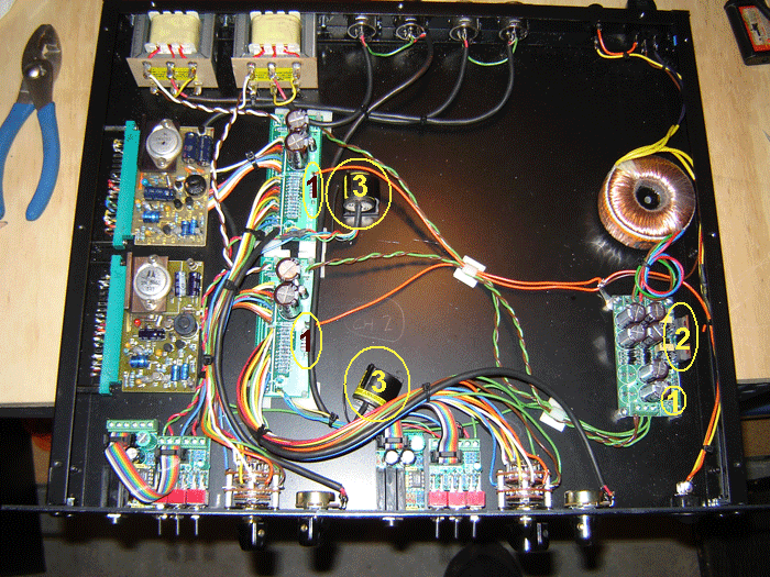
Hi Tim Saw your email. Thought I would put this up here as it might help a few others in there build.
1. You have three 10ohm resistor linking mains ground to audio ground. One on each hotrod PCB and one on the AC/DC PCB. Leave the AC/DC one and remove the other two or just remove the 2 orange wires going to the ones on the hotrod PCB. Remember only one is needed if several modules are mounted in one case. All our power supplies have one 10R with a 0.1uF bypass cap on the PCB.
2. LM series regulators can usually only do about 150mA of current without a heatsink attached. So 2 Neve modules = 220mA. So fit 2 small heatsinks that don't touch each other or use the insulator kits in the AC/DC kit and bolt the regs to the side of the case or a aluminium angle to the bottom of the case.
3. To make a 1:2 ratio transformer to match the 10468 you need 2 x JLM14 per module wired as shown on our 1290 page overlay PDF because the JLM14 is 1:4 ratio. Wiring one straight to the hotrod mod without changing some resistor values will be like setting a 1073 to 300ohm input impedance which is great if you have 50ohm output mics.
http://www.jlmaudio.com/JLM 1290 wiring overlay.pdf
So you could either buy two more JLM14 transformers

or
Change 7 resistors on the hotrod PCB and get 6dB extra gain. The resistors in series that form the input pad setting also are the load resistor to the secondary of the transformer. So with 1:4 ratio will reflect roughly 300 input impedance. So if you wanted to reflect 600ohm you would make each value twice its value or if you wanted to reflect 1200ohm like the original neve make each value four times bigger.
300R - 600R - 1200R input impedance
2k7 - 5k6 - 10k
1k5 - 3k - 6k2
820R - 1k6 - 3k3
470R - 1k - 2k
150R - 300R - 620R
82R - 150R - 300R
110R - 220R - 430R
Yes you do have to be careful with the DI socket. It can only do 3mm panels max and even then you need to make sure the socket is fully forward in the slots on the PCB when soldered in. Also the hole needs to be 12mm so the thread is not deformed when pushed through the panel. Also the hole should be well deburred on both sides and on the front deburring deep so it looks like a countersink helps. A drop of hot melt glue or super glue on the flat front of the socket can help when putting it in and then doing the nut up finger tight + about 5 to 10 degrees is all that is needed. I have looked everywhere is find a PCB insulated TRS with DPDT switch that is better but there is not much out there with that spec.
Depending on the 48v load the 47ohm resistors will run hot. You can always make the resistor smaller to say 10ohms if you want to draw more current as it is just over current protection.


![Soldering Iron Kit, 120W LED Digital Advanced Solder Iron Soldering Gun kit, 110V Welding Tools, Smart Temperature Control [356℉-932℉], Extra 5pcs Tips, Auto Sleep, Temp Calibration, Orange](https://m.media-amazon.com/images/I/51sFKu9SdeL._SL500_.jpg)
