how to gain voltage in a tube rectifier based PSU

GroupDIY Audio Forum

Help Support GroupDIY Audio Forum:

This site may earn a commission from merchant affiliate links, including eBay, Amazon, and others.

mik

Well-known member
GDIY Supporter
Joined
Jun 4, 2004
Messages
473
Location
Milano
Good mornig gentelmen.
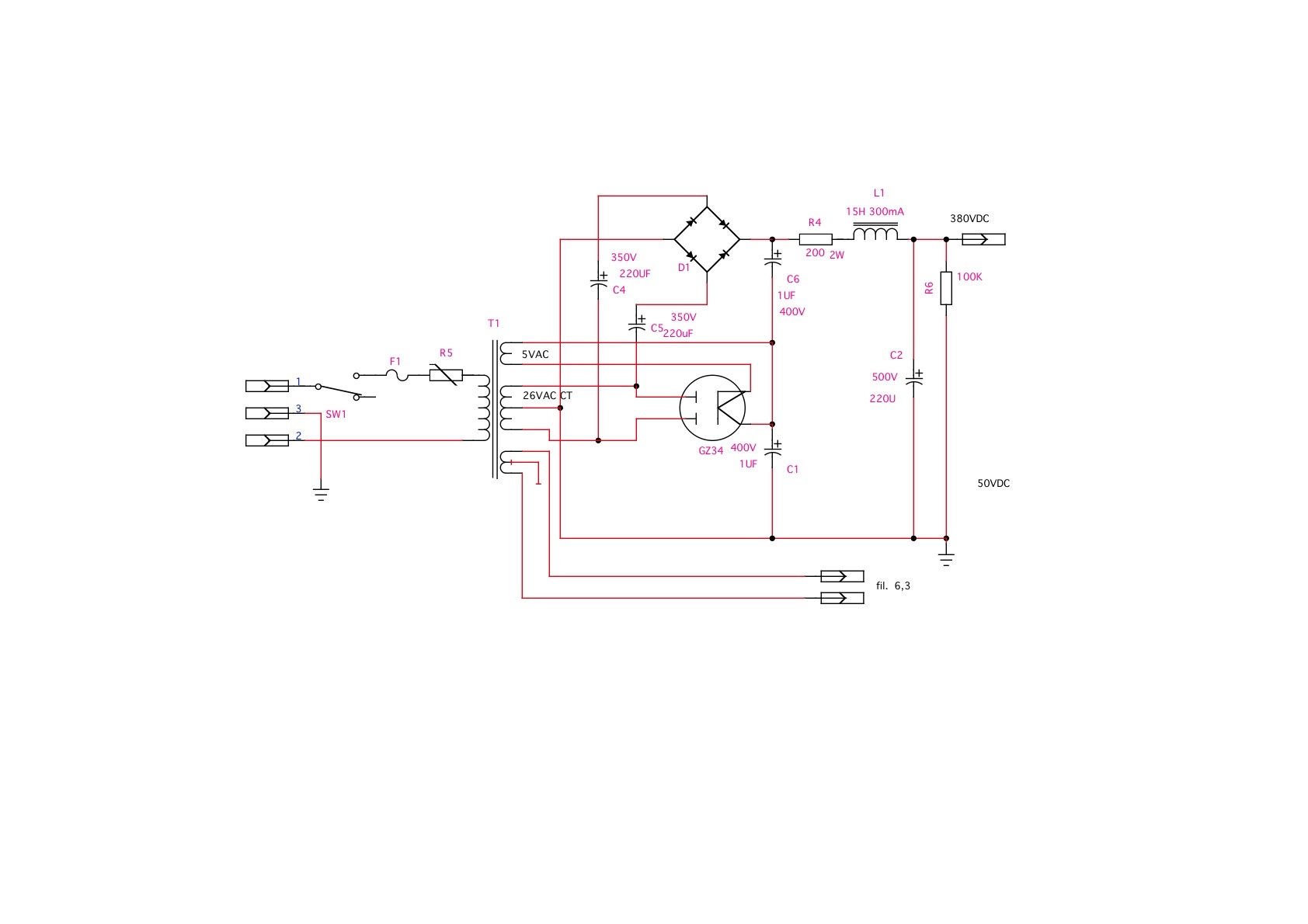
A friend of mine ask to me to gain some more power in his little tube amplifier, obviously it needs more voltage and I've proposed to him a conventional diode based voltage doubler, but he doesn't want to skip the tube rectifier, so I have elaborate a schema, its a double hybrid staked rectifier, but I need the help of someone skilled then me.
can this works ?
thank you
kGCDHUA.jpg


What is he powering, schematic is needed to see how much more V are needed.
For small signals like preamps and compressors, tube rectifier won't make any difference. It can have advantages in push-pull power amps, although solid state rectifier with appropriate series resistor works "same" as tube one. Power tubes can benefit from soft start tube recto does, same thing can also be achieved with solid state components. I tend to leave tube based power supplies in original modules because of looks, new builds have solid state based supplies, sometimes simple AC heating and RC HT filters.
 
You will not get any more power out if you do not put any more power in. Your tube rectifier is only capable of a certain amount of output power. Doubling its output voltage will only halve the available  current so the power remains the same.

Cheers

Ian
 
Again, more circuit details needed. 

If there is significant voltage drop from the rectifier, adding another parallel tube rectifier will raise the resulting B+, but also stiffen any sag, if this is a class A instrument amp.  If you need so much as a voltage doubler, it implies you really need a different power transformer to keep the same basic rectification type. 
 
thank you gentelmen.
well the Power transformer is a 260 V Ac @ 470 mA, the amp pull out about 2.5 Watt at 5% DHT
the aim is to get about 8 or 10 Watt doubling voltage and doing the right mod ( changing load line of the power tubes etc. ) the rectifier tube is jj GZ34 capable to erogate about 700mA with about 17V loss for any anode.
so the problem here is to know if the schematic can works as I've drawn down.
thank you
M.
 
the schematic shown does not work, plain and simple. There is no path for conduction of the diodes.
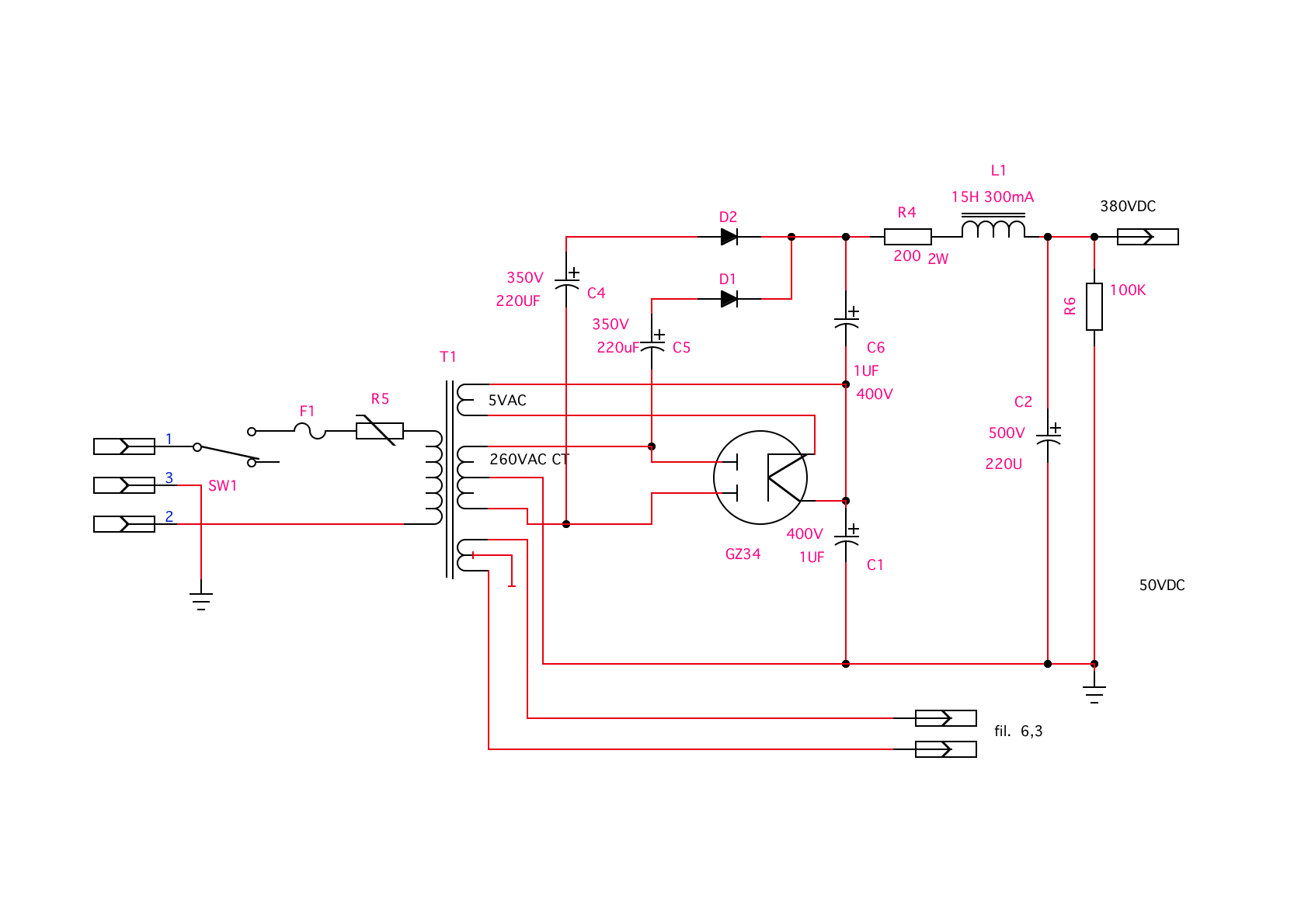
You need to add diodes at the junction of C4/D2 and C5/D1 to ground. cathodes to ground.
 
abbey road d enfer said:
the schematic shown does not work, plain and simple. There is no path for conduction of the diodes.
You need to add diodes at the junction of C4/D2 and C5/D1 to ground. cathodes to ground.

thank you Abbay, do you mean something like this  ?
dHXJZee.jpg
 
In the case below ,simply increasing the value of C304 from 4 to 8-47uf will give you an incremental increase in the ht voltage , maybe thats good enough for what you need .

Duncan's amps PSUD2 allows you model transformer/tube rectifiers nicely .
 

Attachments

  • 670 psu.PNG
    670 psu.PNG
    34.2 KB
Tubetec said:
In the case below ,simply increasing the value of C304 from 4 to 8-47uf will give you an incremental increase in the ht voltage , maybe thats good enough for what you need .

Duncan's amps PSUD2 allows you model transformer/tube rectifiers nicely .
Thanks tubetec
 

Latest posts

Back
Top