Hypothetical Attempt at V76M boards

GroupDIY Audio Forum

Help Support GroupDIY Audio Forum:

This site may earn a commission from merchant affiliate links, including eBay, Amazon, and others.
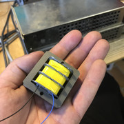
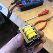
A friend started winding replacement inductors for V76s some month ago. We measured some of his coils a few weeks ago and they seem to be spot on within specs. I´ll invite him to pass by in this thread as he´s a member her, but not posting much. Maybe he can contribute a bit.
 
HI There Guys!

My Friend Jens gave me the info for this thread.

I Rewind and manufacture 100% New Drop in replacements for V76 and V72 Chokes.
These were tested in a original V76.

See pictures:


I Also have a Working 5-CHamber prototype, tested in the original units.


Making the BV515 is also possible, allthough I'd maybe use a bigger M core and not a EI core.

If you are interested you can mail me:

[email protected]

Or PM me.

I am also thinking of setting up a store in the white market maybe?
If interest is big enough.

Best,

Felix

 
MrDude said:
HI There Guys!

My Friend Jens gave me the info for this thread.

I Rewind and manufacture 100% New Drop in replacements for V76 and V72 Chokes.
These were tested in a original V76.

Great news indeed, Felix. I will be emailing you soon.

Thanks!

Paul
 
Winston O'Boogie said:
I received the chokes from Felix.  Beautiful job.  Reminds me of the type of work done by a watchmaker or a maker of precision parts for a Leica camera.

I haven't been able to test them yet, but I did have a friend unsolder and measure original chokes in two V72S modules which came from a REDD.17 desk.

From these rough measurements, Felix's work is spot on.  I don't expect any surprises when I use them

One point which I was a little uncertain on but Felix set me straight is:  hook up the wire that's the end of the winding on the last coil to your anode for the lowest capacitance.
In my case that's the blue wire to anode.  Black wire to H.T./B+

Over & out.

Great news, Winston.

I will be ordering some of these when I get closer to completing the board layout. Are you going to use them for the Bv515 position as well? I was told by Felix he was only doing Bv514 currently as the 515 was a bit more effort but you had mentioned earlier that it one might could make the decision to just use the same value for each position. It might be less accurate but it would/could still sound amazing.

Thanks!

Paul
 
Winston O'Boogie said:
Wanted to put in a good word for Felix.

I messaged him on Friday about a couple of V72 inductors.  After a quick chat I sent him the dosh,
which was a good price for what's involved. 

Anyway, he emailed me Sunday lunchtime  (2 days later) to let me know they're done!

Obviously I don't have them yet, but from what I see, and what he talked about, they seem spot on.
I can't wait  :)
Thanks Felix

For those of us interested in this project can you give us an idea what they cost?
 
I got a little distracted over the last couple of weeks which kept me from working on this potential project. I've attached where I've landed on for a layout. The goal was to keep off board wiring to a minimum. The XLRs, input transformer, and all of the tubes are on a separate board that is mounted to the back panel, with the tubes being accessible without the need for opening the unit. The Input transformer is also mounted on the same board behind the input XLR to minimize the distance between the input and the first tube stage. There are relays for controlling +48V and the high/low gain function, which inserts a U-pad that is shown on the gain switch in the normal schematic. I thought about doing a polarity switch, but I can't remember the last time I needed a polarity switch on a mic preamp as I do all of that in post. If someone needed it they would add it between the output transformer (T2) and the output XLR.

On the PCB with the inductors, the gain switch and relay controls for high/low and +48V are on the board. There will also be a place to add the 0-5dB gain switch if so desired. I plan on only using a switch for +3dB in the section which is half way between the gain selections and fine enough of a control for my needs. I don't know about adding a space for a variable T-Pad for the output or is there is a way to use just a potentiometer for trim. There is also a section for connection points to add a HPF. I also reckon that if one could also add a simple passive EQ at this point. The gain for V3 might have to be adjusted to accommodate this.

The last of the puzzle pieces are the inductors. I plan on using Felix's BV 514 and am incorporating it in the PCB layout. I've pestered him again about BV515's and if he would require a minimum order to consider retooling for this inductor. Right now Lundahl seems to be the best option and fairly readily available but will require some creativity if I wish to mount it on the board. Maybe I need to look at some sort of universal mounting option and use inductors with flying leads.

I did consider trying to make the rear mounting PCB fit a 1U case, but then that would limit what could be used for inductors and output transformers. It would also make the components more crammed together and require more creativity with the board layout. I figured being able to build a stereo V76m into a 2U chassis is pretty good, especially being considering one is able to use a shorter depth case.

I am meeting a guy to look at circuit design on Tuesday to look at this and finish up another project which I will be posting here soon. I welcome thoughts and criticisms or if anyone wants to point out something I've missed.

Thanks!

Paul
 

Attachments

  • V76 layout.jpg
    V76 layout.jpg
    411.6 KB · Views: 72
The original used a three deck switch for the gain with eight gain steps and a pad. I built one with the pad taken out to a separate switch, and the gain steps increased to 24 steps (2 dB steps up to 76dB max gain). Then the gain switch only needs a single deck. And it will work with a DI. The DI input needs a blocking cap to the grid since there is DC there.
Jensen JT-10k61-1M works well on the output and I also used a Jensen on the input.
I wonder if you could find a cheapish transformer like a Antec that would measure close enough to use for the chokes (using only one winding of the transformer).
I used Wima MKP film caps including #35. They are big but work well. I had some so I don't know how expensive they would be however.

If you leave out the filters you do pick up some gain (6dB I think). Your sketch with the 100k trimmer will lose about 4 dB.

You can see my build here:
https://groupdiy.com/threads/v76-tube-preamp-build.68498/
 
Meeting the noise specs for a V76 is challenging. I had to make mu metal shields for the inductors. If you mount them on the pcb you might be limited in what you can do vs mounted with leads. But if you buy inductors with good shielding, then you'd probably be OK.
Mounting the PSU externally could save you a lot of headaches. I had the PSU in the box, and had to shield the toriod PT as well.
Still, putting two in a 2U box is ambitious. Cool and possible though, I think.
 
Having been gifted some EF804S-TELEFUNKEN tubes ( nice gift considering their eye watering cost-approx £120 per!), I thought I might take a crack at building some channel modules to go into the console I’m currently attempting, based on @ruffrecords mkIII console. I thought it might be interesting to compare the v76 with his updated valve design, which he has said was inspired by it.

This looks to be the most recent and pointed discussion of V76 build and I thought I might ask a few questions about the design.

The first, is whether I can power this v76 circuit using the power supply I have built for my console(Ian’s HT350). It provides ~300v of B+ with plenty of current, as it’s meant to power up to eight channels of valve pres. in addition to 48v, it also has 12v secondary, so I planned to use a small transformer on the v76 channels to step that down to 6v for the heaters, and also use the 12v to power relays( just realised can’t use a trafo for DC DOH!). The v76 schematics look to cite very specific values for voltage and current. Is it feasible?

- Richard
 
Last edited:
V76 schematic calls for 300V from the rectifier, so you are good with that

For stepping down the filaments even a simple regulator circuit based on LM317 rated at 1.5A should be fine (one on each V76 channel)

I think it would be better powering the filaments from a separate supply, and not share it with relays, leds or other things that can generate noise in the filaments.

Is the 12V rail on Ian's supply meant to power both filaments and relays ?
 
The three ef804s need 6.3v +/- 5% and 170 mA
6v is a on the low end.
The E83F needs 300 mA.
Total tube heater current 810 mA, as long as you can provide this you are ok.
I would personally suggest a filament transformer 120v -> 6.3v as they are easily obtained. DC for filaments is not necessary imo
Not sure what you are using relays for in a tube preamp?
 
…I would personally suggest a filament transformer 120v -> 6.3v as they are easily obtained. DC for filaments is not necessary imo
This won’t work in this case as I have an existing power supply and backplane supplying dc 12v to the channel connectors. What I need is a circuit on the v76 pcb that will translate 12v to 6.3v. It looks like perhaps a resistor circuit (capacitor, resistor, zener) , or the LM317 as suggested by @beatnik, to bring down the voltage. I will have to eat the heat.

Apologies for the thread drift - I will get back to my questions about the v76 circuit itself presently…

- Richard
 
Last edited:
The various versions of v76 circuit has my head spinning - not that that takes much to do...

From what I can glean on the www, the two versions of the circuit which don't have fixed frequency attenuation, are the V76M and V76S ; that these two versions have linear frequency response. The version which is being focused on in this thread appears to be the 'M' version.

Here's what Oliver Archut had to say about the 'M' version (I am taking it that he was the prevailing authority):

"The 'M' version was released as a reference amplifier or better measuring amp indicated by the 'M' the german word is 'Messverstaerker'. Technical speaking and entire different amplifier, output and tubes are the same, input and front amp are different as can be. Input x-former is 10kOhm impedance, and max. gain is 60 dB. About 600 units were made."

and later on

"...the V76M is not a mic pre, even if it can be used as one. The high input impedance (10k Ohm) can be very unstable if used as a mic pre, but also can shine and boost the mic to the next level.
The front end circuit is quite different as well as some other minor differences..
"
( taken from The different V76 models)

My first question is how does the M circuit 'input and front amp' differ from that of the S version (or the others)? Also, is that front end topology part of what is being discussed in this thread, or is it other aspects of the 'M' circuit that are being grafted onto the 'S' circuit, or even the original V76/80,120?

Lastly, There is some discussion of removing the BV517 inductor (BV519 in the 'S' version?) which comes before V3, 'as it would affect the HF response'. I had thought that the 'S' and 'M' circuit were meant to be linear. Presumably the removal would indeed affect the HF response, making it no longer linear, or at least linear in the way the original design intended. Is that incorrect?

- Richard
 
I believe the 'S' version meant Studio, and was a better version over the broadcast. You can remove the filters in the middle section including the bv517 and it will be linear.
They are switchable for the LP and HP and then the C-L-C is a high frequency limit, if I remember right. CJ has a post somewhere about it.
You get 6dB of gain back with it all gone since there are two 40k resistors in series leading to the 80k, just put in a suitable blocking cap (>0.5uF).
Leave the 80k
I don't have the different schematics in front of me so I don't know what front end differences you are talking about for the 'M'.
 
Here is an outline of the V76 versions I found on the Vintage King website:

V76: Also known as the King Daddy of mic pres. Designed and manufactured by TAB, introduced in 1956, and the head of its own sub-family. Essentially the V76 is a pair of V72's in series, capable of 76 dB of gain, (hence the name). The gain is switchable in 12 steps of 6 dB increments. The V76 has a shelf EQ at 80 Hz and 300 Hz, or a combination of the two.

There are also built-in cutoffs at 40 Hz and 15 kHz (these can be bypassed to realize frequency response from 10 Hz to 35 kHz, but it is arguable if this mod is desirable or not.). The gain circuit combines variable feedback and input attenuation to provide low noise across the gain range. The higher gain is thanks to an E83F pentode and a trio of EF804 tubes, instead of the pair found in the V72.

V76/120: Introduced by TAB in 1960, this model has a shelf EQ at 120 Hz, and also at 300 Hz, as well as the ability to combine the two settings. Nearly identical to the V76, except for the different filter choke for the cut off frequency. This unit was designed for television studios and became a standard in TV production.

V76/80: When the V76/120 was introduced, the original V76 began to be called the V76/80 to distinguish the two at a quick glance. This is why early units are engraved V76, and later units as V76/80. The changeover occurred somewhere between serial numbers 1050 to 1175. The V76 and the V76/80 are the same unit.

V76/S: Also introduced in 1960, with the 'S' standing for Schallplatte, i.e., vinyl LP. This model was marketed to disc cutting labs and provides a frequency response from 20 Hz to 20 kHz. It has multiple cutoff frequencies of 8-10-12-15 kHz, and 30 - 60 - 120 Hz. The cores for the filter inductors are made from nickel/iron alloy, rather than the ferrite cores in the normal 76/80 and /120 models, therefore their tone is different.

V76/M: This model was intended as a precision laboratory amplifier, thus the M indicates 'Messverstärker', or 'measurement amplifier' (not 'mastering' as is commonly thought). As you might expect, these were very different from the standard V76 amp, including no input or high/ low filters, an input transformer set for 10 kOhm impedance and only 60 dB of gain, available in constantly variable 1 dB increments. Precision was a must with this amp, so the frequency response is linear from 20 Hz to 20 kHz. A rare model with maybe 600 units made.

V76/F: This rare model was introduced much later and used in larger consoles with remotely controlled gain, hence the letter F standing for 'fernsteuerung', meaning "remote control'. Does not have the filters found in the standard V76/80 or 176/120.

-Richard
 

Latest posts

Back
Top