I need some help sorting out some triads for an LA2A build

GroupDIY Audio Forum

Help Support GroupDIY Audio Forum:

This site may earn a commission from merchant affiliate links, including eBay, Amazon, and others.

substitute

Well-known member
Joined
Jul 14, 2004
Messages
505
Location
PHILADELPHIA
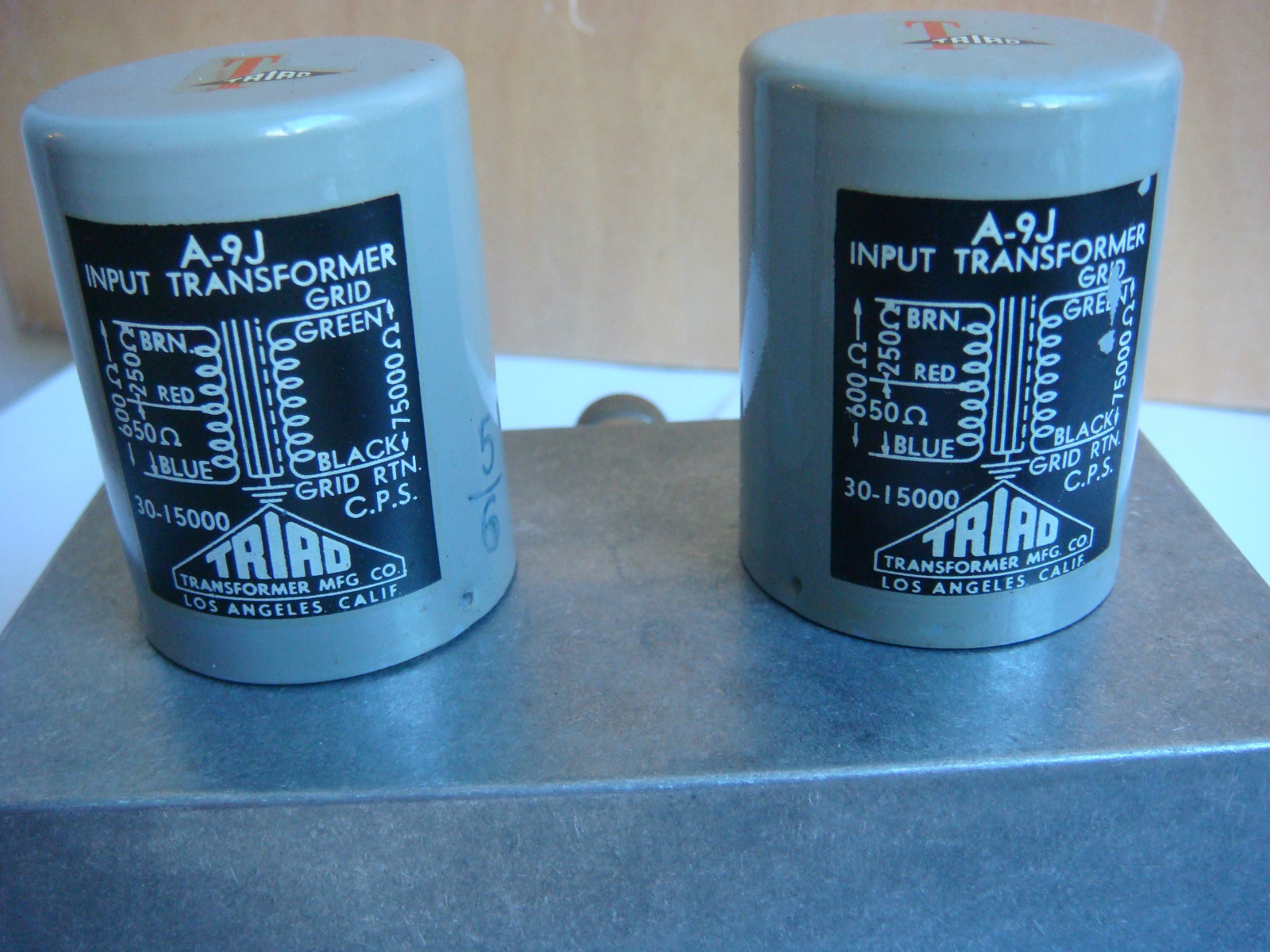
Hey folks, I just fired up an LA2A build I've been working on, something pretty wrong is going on, I'm getting no real signal just lots of buzz.  I want to verify that I've got the transformers wired correctly, since this is where I diverged from the original.  For the input I'm using a Triad A9-j.  I've attached a pic I grabbed from the web, it clearly shows the pinout.  The way I have it set up is..

Primaries
Brown to XLR pin 2
Red CT not connected to anything
Blue XLR pin 3

Secondaries
Green to R6 (and on into the circuit)
Black to Ground
Shield to Ground

Does this look right?

triad-a-9j-mc-transformer-2.JPG

 
Unfortunately my scope is busted, new one arrives friday.  But for now to test it I'm feeding the primaries a 1 volt 1k sine wave I'm measuring 4.4 mv at 60hz on the secondaries with my meter.  Thoughts?
 
60Hz?  Are you testing it with the unit powered on or connected to anything (other gear, test gear, AC outlet but turned off)?

De-solder the wires and measure DC resistance of the windings.  Primary should be around 33 ohms and secondary around 3450.
 
The gear was not powered on at the time, not plugged into wall AC, and not connected to anything else on either end.  However the transformer was in the circuit still.  I'll disconnect it completely and report back, thanks so much for posting those measurements, that'll be a big help.
 
Well, with the input transformer totally removed from the circuit it's a very different story.

DC resistance is ...
22 ohms across the primaries, 4,200 ohms across the secondaries

Feeding 1v 1k sine wave I'm getting 16v on the secondaries, frequency response is normal.

In a sense, good news, I'm taking it that the transformer is fine, however my build probably not so much.

 
Got my new scope and made some progress saturday.  Nothing too interesting but I'll post some details incase someone winds up in a similar spot.  I'm testing it without the T4 cell in, not really worried about gain reduction yet, just trying to get the amplifier sounding good.

-I wired the gain and reduction pots backwards.  So I, thinking I had the GR at "zero" I was actually shorting the input to ground.
-Not sure what was up with the input tx wiring, after testing I hooked it back up and it's fine.
-The input tx I'm using has a higher windings ratio than the standard LA2A,.  It's still meant for line to grid, but now the input is REALLY sensitive.  Once I got a test signal passing through it seemed to distort too easily.  I'm thinking I'll use a 12aY7 for V1.
-I forgot to strap a 600 ohm load across the OT, adding this cleaned up the waveform a lot

I haven't tested it with music yet, just a function generator, seems like I'm on the right path though.
 
Back
Top