> jeezus h, ???
That's all in there when you wind.
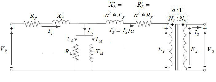
Rp is primary DCR, what you were asking.
Rc is core loss, small on thin lams (but on huge power transformers can add-up to a bunch of idle heat).
Xm is primary inductance. On a laminated iron core, this inductance *drops with frequency*, as you have often shown by test. (The reactance rises, but less steeply than expected for a constant inductance.)
> Make an RLC notch filter
At what frequency??
I think he tried to resonate it, at hundreds of Hz, and got answers he did not like (implied poor performance). Testing again with simple resistance reference, he got numbers he liked (implied performance better than specified, and that is what we expect from good parts). I think if he tried to resonate it in the 20hz or 40Hz area, he'd get the same/similar inductance numbers. (Different because iron-core inductance varies with level, another CJ curve, and resonances change level quickly.)
Tuning a big coil and core to 20Hz is likely to require dozens of uFd. Which will probably be an Electrolytic cap. (Hardly worth buying huge film caps for one test.) E-caps are perhaps the second most UN-ideal parts in our bins. I remember +100%/-50% tolerances. There's some voltage coefficient (not as much as the worst ceramic dielectrics). They leak like my water cooler. They love to eat reverse voltage and die.
Put it between the resistances you are gonna use it at and take a full response curve. Same as any passive black-box which you suspect of being un-flat.


 I guess I would never trust them for any kind of design.