or for simplicity I could install the regulator to set the voltage to 30v and just plug and play, the 2604 would then be close to its nominal voltage, which surely is not a bad thing?
Yep that will work.
There are 6 prongs on the power switch. Do I run pos and neg from pre to 2 prongs ,pos and neg from power socket to 2 prongs and , pos and neg to the green LED? What side do the red and black go?
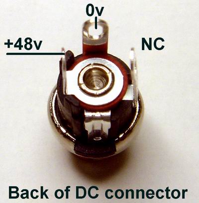
What is the config on the rear power socket. There are 3 prongs. Do I bridge something? Also What is the right orientation for the red LED's that ge attached to the Phantom legs?
HI Nick did you get this all sorted from the email I sent you?
Does anybody here already tried the BA with some melcor 1731?
i'm willing to try given that i have few boards...
any comments?
Will work fine from the circuit I have seen for the 1731 with the opamp reg set with a 33v zener to give +/-16v.
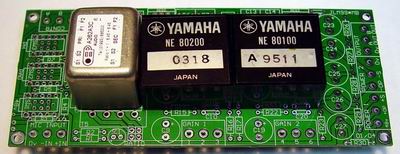
There was some discussion about whether using Yamaha NE80200 opamp with the BA was feasible, a problem being the power requirement of the opamp. Have these been tested in the circuit?
They should work but I have not tested them. Also they are bigger than 1.1" so will only fit well on the BA but they will work and fit on the original JLM99*MB used for the Dual 99v.
I'm finished stuffing the BA boards and the hybrid doa boards. Powered up the board - voltages seem ok so I put hybrids in - class a-a/b switch seems to work ok but the 2604 and transistors are hot - not cooking but uncomfortable to touch for more than 2-3 seconds - have not tryed passing audio yet - should they be this hot or have I done something wrong?
The OPA2604 at idle on 48v is putting out about 0.5watt of heat. So yes it is hot. And each output transistor in Class A is putting out 0.75watt of heat. So yes they are hot as well.
Well at least hot to a humans touch :wink:. So yes all is fine.
Two of the 10k rev log pots that I received are broken (i.e. they don't turn).
Umm strange as the only time I have seen one these pots lock up is when the locating tab isn't cut off and the nut is done up tight on the bush and it bends the bushing as it is tightened because the pot will not sit flat against the front panel. Was there something stuck in the pots? or any other clues? As it is strange it is two pots that are faulty.
whats the difference between the DUAL99v and the BA99v? is it just more gain? or is the sound completely different?
Mainly the Dual 99v can do 80dB gain with ease and also can have a gain trim or fader inserted in between the two 99v's.
Is the dual99v much harder to build than a baby animal?
Yes as you have to build a power supply for the Dual 99v but the Baby Animal runs on a prebuilt 48v SMPS.
if fitting a screening can to an OEP transformer, should the can be soldered to the screen pin on the transformer to ensure connection?
Yes
If i don't use an output tranny with the BA, will my signal be unbalanced?
No it will noise cancel like a balanced output if it is going to a balanced input due to the XLR pin 3 sending a noise reference. The same idea is used on the output of a GML EQ and some modern Neumann Microphones.
I've put in the BD681 and a 33v Zener diode, but i'm only getting 9.8v volts on the op-amp sockets......I'm looking for around 16v really......
My power supply is the 48v smaller one.
Anyone else had any problems like that?
Should I just change the zener diode to a higher value until I get a higher voltage??? Or what about the #10k? How does that effect things????
Sounds like the opamp isn't fitted and your meter isn't drawing enough current to turn on the BD681 fully so you are getting a phantom low voltage which will go up when more current is drawn. Put a 4.7k resistor between _V and +V on the opamp pins and see if the volts comes right. If not either the zener or BD681 is faulty. The #10k value works for all zener voltages and doesn't need to be changed.
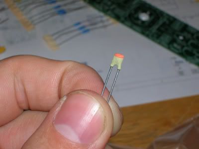
I do have a 220pf in my kit BUT:
The table says that CL should be 390pf for jlm114 AND OEP.
What's up with that? I need the answer for jlm and oep as well (I'm building this one next), all I have is 220pf's!!
The 220pF value is right for all transformers and opamps if normal RL from the tables is used but if you add variable impedance then CL will need to be changed to 390pF where shown for the BA to stay stable at full gain.


