JLM Baby Animal

GroupDIY Audio Forum

Help Support GroupDIY Audio Forum:

This site may earn a commission from merchant affiliate links, including eBay, Amazon, and others.
Cleveland : That looks great! What did you use to fill in the excess holes on the B*ringer front panel?
 
[quote author="tazwolf"]Cleveland : That looks great! What did you use to fill in the excess holes on the B*ringer front panel?[/quote]

I think he glued a vinylsheet to the front.

Very very beautiful!
 
Actually it was peel and stick! easy.

After using these for two days I can already say I have a new go-to pre for guitars - the OEP/99v is just unbeliveable, even with a 57. The JLM/99v is much more colored to my ears and sounds very much like my buddy's 1272, I'll have to borrow it for comparison. The low end just oozes out of it, goopy.. very cool. I'm going to add a DI to one of these channels and I may add output transformers to both, I think they'll be fantastic for tracking bass. I may build another pair OEP/hybrid, I have a notion it may be the hot ticket for drum overheads.

maybe down the road a jensen/990c pair.....

Sorry for the commercial, but these really are no-foolin' fantastic! Cheers to everyone at JLM for making these available for cheap!! I'll put a pair of these up against anything I've ever heard.
 
I already have most of the parts needed for some BA lying at home. So im trying to source all the remaining parts i need locally.
I cant seem to find a low impedance 470uf/50v capacitor anywhere that is also 10mm in diameter.

The only thing i can find on farnell is some Panasonic NHG type A caps.

These dont seem to be low impedance though.

Will they work, or will i have to order everything from Joe? (which i certainly wouldnt mind, except maybe for the big fat import tax im going to have to pay in that case)

/Jonas
 
Jonkan,

For most of the caps you can use a 35V rating. The voltage over those caps is only 24V because of the voltage divider. The 2 you have to be careful of are the input cap and the +48V cap. I have used a 220uF/63V for both of those, the 220uF instead of the 470uF will only effect the ramp time of the +48V rail.

I have built around 6 Animals this way and all is going strong. I use the Rubycon YXF range, long life, high temp and low ESR caps.

Cheers

Matt
 
cool!
The rubycons i can get here.

So basically i need 4x 470uf 35v caps, and 2x 220uf 63v.

Which cap is the input cap btw, and what does it do?

I cant seem to find a 220uf 63v rubycon btw. So ill have to use something else for that!

Also, has anyone tried using beyer input transformers for these pres.

I have 4x 1:10 transformers lying around that im going to use.

I was mainly wondering about the loading and/or zobel network for these transformers.

/Jonas
 
Looked for the jumper and RL, CL, RZ, CZ, RPAD, and RG values for the Cinemag CMMI-8-PCA, but couldn't find them on the chart on the JLM website or the two Baby Animal threads here.

Could I get these values? I'm going to start stuffing 4 boards tomorrow, one of which will have the Cinemag.

Thanks,

Craig
 
3.jpg


Now that is Cool :grin:

I'll be ordering another 99v because I bridged the output cap to ground... oops.
Did the 99v smoke totally or is it just making a distorted output now? Did the 51R go open circuit or burn?

Nice kit, couldn't be happier.
:grin:

FYI, the OEP kits need another computer jumper to be totally complete. no biggie.
Ok will check the kits that are packed here as they should have 4 jumpers in each kit. With a JLM14 no ratio jumpers need to be fitted. And my favourite setting for OEP is one jumper which is 1:6.45.

Sorry for the commercial, but these really are no-foolin' fantastic! Cheers to everyone at JLM for making these available for cheap!! I'll put a pair of these up against anything I've ever heard.
:cool: :grin:

Also, has anyone tried using Beyer input transformers for these pres.
I have 4x 1:10 transformers lying around that im going to use.
I was mainly wondering about the loading and/or zobel network for these transformers.

Most production uses for the Beyer transformers that I have seen only have a RL of 150k and no CZ or RZ. With some opamps you will need CL of 220pF.

So basically i need 4x 470uf 35v caps, and 2x 220uf 63v.

Which cap is the input cap btw, and what does it do?
BabyAnimalPCBCVCJS.gif


The 4 caps marked as 35v can be that voltage on 48v or 62v power supply. The one marked 50v needs to be that on 48v or 62v power supply. The one marked 50v or 63v depends on the power supply voltage as to which one to use. All JLM kits ship with a 330uF 63v cap for this position just to make packing here easier.

Looked for the jumper and RL, CL, RZ, CZ, RPAD, and RG values for the Cinemag CMMI-8-PCA, but couldn't find them on the chart on the JLM website or the two Baby Animal threads here.

Could I get these values?

From the Cinemag PDF here
http://www.cinemag.biz/mic_input/CMMI-8-PCA.pdf

There is only one primary winding so no ratio jumpers are needed.
RL = 100k RZ = 9.76k CZ = 22pF RG of 68ohm will be fine and RPAD can stay at 100ohm is you want a 20dB pad or smaller value is you want a more dB pad.
Also remember when using Cinemag and Jensen transformer that need pin 6 & 7 pulled to 0v ground to add the black strap shown on the gif above under the PCB.
 
Since fitting the regulators and a switched zener to 2 channels of BA's I have hi pitched oscillation.

its not there all the time and changing the gain makes it come and go and change pitch. high and low gain settings it goes away, mid settings where i'd normally use it its there.

moving the gain pot wires affects it too, the gain pot wires go quite near the switch and wires from the board for the switched zener. its doing it with the zener switched out of circuit at present so the regulator is not dropping the voltage much.

could the regulator be causing the problem?

EDIT - with the zeners switched in it doesnt do it, so is it something to do with having a regulator fitted and the zener switched out? or is it just that it doesnt do it at the lower voltage?
 
Correct me if I'm wrong...but isn't there an API-ish configuration for the Baby Animal?

I really want that vein of sound, but according to another post...it isn't that simple without buying the real thing.
 
[quote author="JLM Audio"]Also remember when using Cinemag and Jensen transformer that need pin 6 & 7 pulled to 0v ground to add the black strap shown on the gif above under the PCB[/quote]
I guess this is also needed when using the CM-75101APC?
I didn't realisze that one? :oops: Maybe i should be more observant. :wink:

Also, so far with this tranny I've just copied what you've suggested for the LL1578 at the 10:1 ratio.
I' had a quick look at this on the cinemag page, but it's definlitey not as detailed as the pdf for the CMMI-8-PCA.
CM-75101APC.jpg

So I'm guessing. nothing is needed for the RZ or CZ, but Should I be using 15k for RL? It seems quite different than the 220k I've used.
But looking at the CMMI-8-PCA, I'm thinking that has more to do with the impeadance ratio, rather than the RL needed......... I'm prob just confusing myself.... ha ha
Everything sounds fine, but I'd thought I'd double check on these two questions.

BTW, I got everything going with the 2520 combo too, so :thumb: :thumb: . Hopefully I'll get a chance to try it out soon along side the cinemag /99v combo, and see how they sound next to each other.
I've gotta do some drum samples at some stage to chuck into drumagog(yeah I know it's cheating, but it helps when ya gotta record some band with a shit kit.........ha ha), so I'll have one of those days where you try all your different mic/pre combos and spend the day goin "doof, doof, thud, Boing"

Oh, and one last question :roll: , not directly realted to the Baby A, but, I've got my output wired with a balanced transformer output as well as an unbalanced out. Besides the extra gain, and when i match up the levels on the two going into pro-tools, I don't know if i can honestly hear the difference. Maybe. But ever so slightly.............. Which makes me ask, if we can do the quasi balanced thing like you've suggested, are output transformers really nessecary for home studio's like mine where everything is generally done over short distances?
I can't remember exactly which tranno it is. CMOQ somethin. It's nickel.

Anyway. I have space for one more baby A in my rack, the tough choice is what version is it gonna be............ ha ha
I think i may just have to give your tranno a go sometime in the not so distant future Joe. :green:
 
EDIT - with the zeners switched in it doesnt do it, so is it something to do with having a regulator fitted and the zener switched out? or is it just that it doesnt do it at the lower voltage?
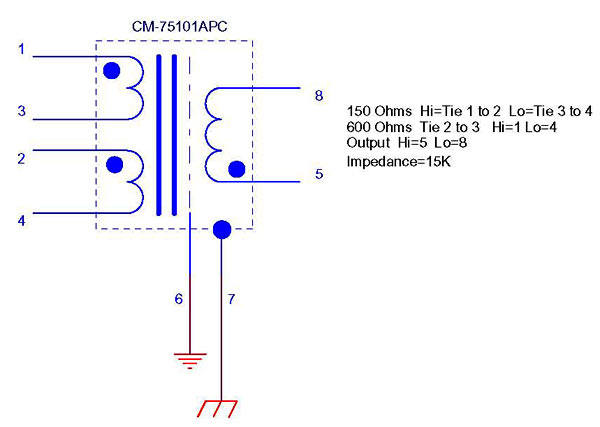
Try adding a 0.1uF cap across where the zener would be on the PCB and see if this fixes the problem when the zener is out

Is the ground and center pin on the 10k gain pot supposed to be connected
Looking from the front of the pot with the pins down. Join the left and centre pins. Now join the gain and 0v to either the joined 2 pins or the left over pin. Either way around will work fine.

Correct me if I'm wrong...but isn't there an API-ish configuration for the Baby Animal?
You can build a 312 type pre on the BA PCB but you will need a 2520 opamp and transformers to suit. Use the API 312 thread to work out which transformers to use.
http://www.groupdiy.com/index.php?t...torder=asc&highlight=api+transformer&start=15

I guess this is also needed when using the CM-75101APC?
Yes

I' had a quick look at this on the cinemag page, but it's definlitey not as detailed as the pdf for the CMMI-8-PCA.
Yes I thought this was odd as well.

So I'm guessing. nothing is needed for the RZ or CZ, but Should I be using 15k for RL? It seems quite different than the 220k I've used.
Yes 15k will reflect the 600ohm with the primaries in series. But I would try adding a 500k log pot in series with 15k and have a listen. But yes there is no clue if any CZ or RZ are needed.

Oh, and one last question , not directly realted to the Baby A, but, I've got my output wired with a balanced transformer output as well as an unbalanced out. Besides the extra gain, and when i match up the levels on the two going into pro-tools, I don't know if i can honestly hear the difference. Maybe. But ever so slightly.............. Which makes me ask, if we can do the quasi balanced thing like you've suggested, are output transformers really nessecary for home studio's like mine where everything is generally done over short distances?
A good output transformer shouldn't add much to the tone of a pre it if it is made well besides adding the extra gain if wired as a step up ratio. All gear only needs to be balanced in for noise cancelling to work as long as there is a noise pickup wire coming from the signal output. Even a expensive GML or Sontec EQ only has Quasi balanced out as it is the purest minimalist way out.

Anyway. I have space for one more baby A in my rack, the tough choice is what version is it gonna be............ ha ha
I think i may just have to give your tranno a go sometime in the not so distant future Joe.
You cannot live without one of them :wink:
 
I have some more questions before i order stuff, if you all have the time to answer :green: :

The 0.1 bead...Is it a multilayer cheramic, or a film type cap?

What parts can i leave out if im going to use the Jlm output transformer?

What diameter does the DC jack for the +48v supply need to be?

Is the pot for the variable impedance preferrably log or lin?

Also, would there be any idea in implementing a variable impedance for the beyer transformers? Perhaps someone has tried this?

Im wondering what value would be good for the pot for this...

Thanks a lot for any answers!
/Jonas
 
I'm doing some testing with a signal generator on BA as I have a case of the hums and I noticed that the output is out of phase with the input unless I flip the phase to phase reverse - is this correct or have I done something wrong?
 
Hi,

I just stuffed my first two BA PCBs. One for 1:4 & 99V and one for
1578 & 99V. On both PCBs without the 99V installed I read 0V on
the marked spots where it is said it should be 24V... is this normal?

BA-PCB.gif


BTW the multi cable to the DI is not connected yet and the NF places are left empty.
 
Ups, I tried the PCB with 99V installed but the 10R resistor started to burn ....
something isn't right. Then I noticed that I forgot to solder the small jumper
next # zener place. Fixed, but two Opamp pins are still reading 0V.

I really hope I didn't burn the 99V as well. :cry:
 
Purusha,

Why have you jumpered the Zener diode? You don't need that link, remove it.

Also if you are not using the DI kit you should use the black thumb tabs in your kit and as per the voltages pic, fit 2 of them onto the IDC, look at the 2 yellow lines.

Are you sure you put the right caps in the correct holes? There are 2 x 63V, they need to go in the correct places, and you can work that out by looking at the voltages pic.

What were your voltages like on the caps? Did you check those? It is always good to test BEFORE putting in the opamps as well.

Another thing, just for neatness and to help trouble shooting, it is good practise to choose ONE way to place your resistors and have all the bands face that way, it looks nearer and is easier to troubleshoot.

Just take the project slowly and carefully.

I would remove that zener jumper, check your caps and then replace the 10R and check your soldering for bridges, mistakes etc and power up without an opamp and check your voltages again.

Cheers

Matt
 
Back
Top