JLM Baby Animal

GroupDIY Audio Forum

Help Support GroupDIY Audio Forum:

This site may earn a commission from merchant affiliate links, including eBay, Amazon, and others.
I build today 4 more BAs. Two 1:4 + 99V + 1:1:1, one 1578 + 99V and one OEPA3C + Hybrid. I had to do some trouble shooting but they all work OK now.

I was a bit worried with the hybrid as the LED didn't go off in A/B but then I noticed I soldered the wrong two squares together. I think I soldered the DC servo option instead of the A/B opamp. The two squares in the red circle are the right ones. Correct me if I am wrong :oops:

Hybrid.jpg


One more thing. Is there any special reason of bending the NPN and PNP. I left the NPN a little more in the air as the PNP is down holding the LED tight. I noticed also that they tend to become pretty hot. Is this OK?
 
hello,

I've stuffed a BA with OP2604 and OEP TX input and a BA JLM99V with JLM 1/4 INput TX and also a JLM 99MB with 2 5534 and OEp TX input.
They all work perfectly, and we've tested them with a pair of Audiotechnica condenser.

Lots of gain on all setups, but my problem is when the gain knob is fully CCW there is still amplification i can not "stop" the source.

I need absolutely a gain knob that makes my preamps going between 0 and full gain, on the OPA 2634 with OEP put at 1:12.9 even with the pad on it was still too loud on certain sources with the gain pot fully CCW !!

This is a real problem. Did i connect something wrong ?
For the dual JLM 99mb i have followed the wiring instruction diagram to connect the dual pot, but no way, it reacts like the 2 BAs

I use alpha cranted (those delivered with JLM kits) on all of my preamps

Thanks for helping me
 
No pre that I know has a gain knob that goes below unity gain, and the BA is no exception - thats definitely how its supposed to be.

What is the clip level of your recorder? If its set to -10 instead of +4 input then the pre will appear to have too much gain. If its set to +4 and you still have this problem, you might have to investigate the max input level of your recorder as it may be one of the few that are around +10 instead of +18-24 (Creamware and some other cards are like this).

The other two things you can do if you want are to change RP (the shunt resistor in the pad) from 120ohms to a lower value, perhaps 68 or 91ohms. And of course you can change the ratio jumpers so your OEP is 1:6 instead of 1:13.


M@
 
The sound card was a MOTU 2408 (old model), with 8 unbalanced inputs, but i can't find the manual to check if the input line level of the sound card is the problem or something else.

An other idea is to put a variable pad or an output attenuator ?
I don't know what to do.

Any suggestion would be appreciated.
 
I've said for years that the interfaces generally clip too early.
The makers argue that you need to be able to ring the bell if you want/need too.
I think,
leave the BA as a standard build and make an input pad for the interface is the way to go

this can be a simple passive unit and could include a transformer for extra options
use switched to bring the options in and out
it should be able to drop the level of incoming signals and terminate the line with 600 ... perhaps even a couple of choices 600 and 1.2 k
it could even have an earth lift
it could try to cater for unbalanced situations

interfacing equipment is still such an important topic and so many continue to get it wrong
(not necessarily those here ... but out there ... in the real world ... including the pros)
 
Kev,

I think i'll put a 4pos 3 poles switch in a H pad config with 600ohms (switchable) termination with -18, -12, -6 and 0 dB attenuation at the output of my preamps.

sometimes when i record outside the studio i use crappy recorder with -10dbV inputs so the -12dB will give the +4 to -10 attenuation. The -18db will allow me to turn the gain pot and have more coloration of my jl99v with my hot mikes or maybe -24db would be better ?
Any remarks are welcome

Cheers [/list]
 
add the earth lift

a unit like this is not only useful for the JLM but almost any unit that has more output thant you need

perhaps a patchable pair to leave near the interface

when looking for tone a variable load may also help

again
a portable patchable unit may be good to check what gear you have that does benefit from this ... before you build it in
 
Im trying to decide if im going to build 2 channels of BA with 99v opamps, or if im going to stuff some diy fabio 2520 opamps which i already have pcbs for.

Im not shure how they will differ in sound as i havent heard any of them.

Both are quite colored right? But im guessing the api has a "faster" sound to it, right?

Please help me make a good decision. I like the idea of soldering my own opamps, so thats a plus for the 2520 in my book, but soundwise i have no clue what to expect.

/J
 
and that's why you need to make a couple to find out

remember that these are all DOA in the 312 style of things and in that sense the may all have the same feel
variantions in I/O trafos and DOA aside

they are not Neve1272 or 1290 ... or ALL tubed
and not like an ALL opamp
get my drift ?
 
Before you make an output pad (and youll need to know exactly where your interface AND the BA clips before you can do this properly) you should change RP to 68ohms or less, or even easier and probably the best solution is to change your input transformer ratio down to 1:6 from 1:13.


Jonkan, I describe the sound of the 99V as smooth and warm but at the same time clear and detailed, a very rare combination. The 2520 I dont like as much (nothing against fabio of course!) but it definitely has its uses. It is faster sounding (tho I dont know if it actually has a faster slew rate) and has more 3rd harmonic distortion than the 99V so it has a brighter, harder sound. I like that sound on snare drum and vocals sometimes.


M@
 
OK guys,

Kev, what do you mean by earth lift ? how do you do that ? what is that doing ?

Matt,

The 1:12.9 gives high gain and a different color from the 1:6.45, so i would like to leave it like it is now.

Maybe I can make Rp variable ?

It start to be confusing right now, the only thing i would like is a kind of output level so i can "play" with the gain and the output level to match my DAW input and to "color" the sound a little.

Sorry to bother you but i'm close to what i consider like my ideal preamp.

I would like again to thank you all and especially Joe for his great stuffs

:thumb: :thumb: :thumb:
 
Perhaps i need to make 1 channel of 2520 BA and one 99v to see what i like more.

Not everything has to be in stereo pairs i guess...

:green:
/J
 
I cant remember the last time I used a matched stereo pair of mics or pres in the studio.


Flaheu, high gain is your problem, that is why youre getting too much level into your A-D. A different color is great but not if it means the pre gives too much gain. Yes you can increase the pad value but then all youre doing is wasting all that level just to make it up again with the transformer...

But hey if it floats your boat then go for it.

I would be getting everything working and interfaced properly before worrying about 'color' and playing around with output pads (receipe for other problems and confusion).


M@
 
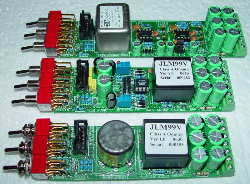
That's a 5K variable resistor (adjusted to 4K7)hanging on the impedance pot. Its all i had going at the time
Either 5k or 4k7 will work fine. Nice case recycle and I like the wild dial pattern around the knobs.

This pre will get lots of use recording drums and electric guitar, it has some sweet low mid warmnes going on.
So much better than my presonus pres!

Im addicted... Thanks Joe and mat
:grin: :cool:

I think the switch with my kit is DPDT (it has 6 connections in rows of 3). How do I wire this switch using a LED (which side of the LED connects to where). I read earlier descriptions in this thread and the response was to wire the top and bottom connections. This doesn't make sense for the switch I have in my kit. I could be having a brain fart though.

Also what type of wire is recommended for this purpose?
Take the 48v from the power supply to one of the centre tags. Then a power wire to all BA 48v from the tag directly under it. That will make the BA's on with the toggle turned upwards. Join a 10k resistor to the BA 48v wire and then the other end of the resistor to the Anode of the LED (long leg) and then take the cathode of the LED (short leg) to 0v. Done.

I was a bit worried with the hybrid as the LED didn't go off in A/B but then I noticed I soldered the wrong two squares together. I think I soldered the DC servo option instead of the A/B opamp. The two squares in the red circle are the right ones. Correct me if I am wrong
That was because in the photo you sent me you had a 1N4007 Diode backwards.
In the photo below the top 2 square pads are servo on when soldered together.
The bottom 2 square pads are Class A/B when soldered together and LED is off.
ALSO WHEN USING HYBRID WITH BA PCB LEAVE OFF 47uF cap on the opposite side of the PCB to the LED. As this can override the power supply filtering and let noise into the pre.
Hybrid.jpg


One more thing. Is there any special reason of bending the NPN and PNP. I left the NPN a little more in the air as the PNP is down holding the LED tight. I noticed also that they tend to become pretty hot. Is this OK?
They will be hot but the one with the LED should be flat with the LED legs short for the thermal coupling to work best.

I need absolutely a gain knob that makes my preamps going between 0 and full gain, on the OPA 2634 with OEP put at 1:12.9 even with the pad on it was still too loud on certain sources with the gain pot fully CCW !!
The sound card was a MOTU 2408 (old model), with 8 unbalanced inputs, but I can't find the manual to check if the input line level of the sound card is the problem or something else.

An other idea is to put a variable pad or an output attenuator ?
A gain pot should with the pad switched on get you close to unity gain at minimum setting. But with the OEP on 1:12.9 and giving 22dB gain + 6dB from the opamp if using 99v or 12dB if using OPA2604, NE5532 you will need to change RPad to 39ohm to make a 28dB pad for 99v and 22ohm for 34dB pad. From memory your Motu 2408 Mk1 clips at +4dBu so to make it into a pro level unit you should add a Pad into the input plug of 2.2k in series with the input and 470R across the Motu input to ground and make a -14dB pad which would give +18dBu 0dBFS like Digi001 and 002 and RME etc.

Purusha got the kits ok. Seems the main problem is the millmax pins with the fat collar at the base do not leave enough room for the 51R in between them at PCB level. Forcing the 51R in will just chip the paint of the resistor exposing the metal cap on the end of the resistor which will short the 51R or the opamp output or 0v or both at the same time. If using these Millmax pins leave the 51R resistor about 5mm above the PCB where the pins are thin again. The pins we supply with the kits are fine with the resistors hard against the PCB.
 
I've got a couple of JH 990's that I planned to use in my BA's. I read an article by Mr. Hardy that the 990 likes to see a low impedence from the input. Most of the transformers recommended for this project have about a 10Kish secondary. Will this affect the performance of the 990?
 
I've got a couple of JH 990's that I planned to use in my BA's. I read an article by Mr. Hardy that the 990 likes to see a low impedence from the input. Most of the transformers recommended for this project have about a 10Kish secondary. Will this affect the performance of the 990?
10k is low and a good number of BA's are already running with JH990 with excellent results.

Thanks everyone Baby Animals Sold passed 500 this week. So I thought I would put up a photo of two new BA family prototypes. The new BA type PCB's run on the same 48v to 62v power rail as the original BA and fit straight into the same position.

BA%20ALL.jpg
 
Hey Joe,

I'm looking at the second board, the NEUTRAL, and it looks like it is a version of this http://www.forsselltech.com/JFETMP1.PDF but with single ended output (2x2SK289, OPA2604, JLM99V as out driver). Am I right? Did you use DC servo for the output circuit? (somewhere under the JLM99V a chip?)
I'm very interested because I started to design a board for something similar, but in this case I would preffer to buy from you.
Give me please more details about the NETRAL.

chrissugar
 
cool!

I might have to get a big box, so that i can build more and more of these preamps until i have an army of them. Cheap and good is definately a plus in my book.

Whats the difference between the dual 99v and the dual BA?

/J
 
Are we still giving away one of these with the 1000th BA kit Joe?

Is is assembled or parts for DIY? Hah hah!!

Well done again gentlemen :thumb: Glad to have been able to support the en devour and look forward to playing with the new additions.

Cheers

Matt
 

Latest posts

Back
Top