JLM Baby Animal

GroupDIY Audio Forum

Help Support GroupDIY Audio Forum:

This site may earn a commission from merchant affiliate links, including eBay, Amazon, and others.
Skipwave is right about the 24v bias is missing.
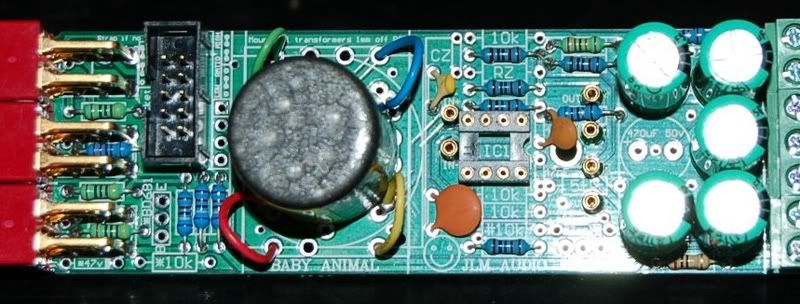
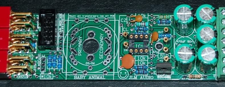
And this is your problem as you have the input transformer secondary tied to 0v instead of +24v half rail
which is used to bias the +in on the opamp to half volts
which then holds the output of the opamp at half volts so it will all work.

Thank you Joe and Skipwave. I did as you suggested with the 1/2 volt (24volt) tie in to my transformer secondaries, as I should have done to begin with by following the schematics like a good boy.

So I have a model of functionality from
one BA using both MM99's and 3 JLM Hybrids with variable gain working. The red light is even on on the Hybrid!

Nice sine wave into line Cinemags at around 400 Hz, and an amplified clean sine wave out of the Baby Animal according to my scope.

The next step is to take the SUMTHING channel sum into a 4 BA boards.
Since this isn't transformer based, I'm somewhat confused. Should the SUMTHING "float" at the 1/2 mark as well? Because when I tried reading the Left or Right outs from the output BA's as tied into the Left/Right channel outputs of the SUMTHING, I didn't get good any signal; while a good signal was injected into the SUMTHING and arriving at the input of the BA output amps. Also Hybrid Opamps didn't light again.

Thanks guys!
-Jay
 
So I'm trying to connect the SUMTHING outputs 1 and 2 each to a JLM Baby Animal (BA), but am only getting the "biased at 0v" spitty short square wave upon giving each a nice 400Hz sine coming out of input BA's into the Sumthing board.

The "master sum/makeup gain" BA's do not have input transformers.  I'm taking only the + out from the summing output, as it is not clear to me what to do with the -.   Maybe that is the key?     The out BA's have input 0v tied to chassis ground like all of the others, and show proper voltages on all of the DOA pins (+48/+24/0).

So guys, ideas on how I should get the "master sum/makeup gain" BA's to amplify this signal without an interstage transformer?  I've not fitted the CZ, RZ,RL, or CL to them, and insert the signal at the top of the CL pad which goes to the + in of any DOA or opamp.    Using tested good JLM Hybrids for this, I get a red LED, then it flickers for some time, then goes off.


-Jay
 
So guys, ideas on how I should get the "master sum/makeup gain" BA's to amplify this signal without an interstage transformer? I've not fitted the CZ, RZ,RL, or CL to them, and insert the signal at the top of the CL pad which goes to the + in of any DOA or opamp. Using tested good JLM Hybrids for this, I get a red LED, then it flickers for some time, then goes off.

When using the BA as a makeup amp with no input transformer. You need to fit RL to get the half volt reference to the +IN of the opamp and then use a capacitor to feed the signal into the opamp +IN. So say you set RL = 10k with a 100uF 35v cap with its positive going to the +IN. Then feed the summers output to the caps negative and you will be up and working. If you don't do this it is the same problem you had wiring the input transformer to 0v instead of half volts.
 
[quote author="JLM Audio"]
When using the BA as a makeup amp with no input transformer. You need to fit RL to get the half volt reference to the +IN of the opamp and then use a capacitor to feed the signal into the opamp +IN. So say you set RL = 10k with a 100uF 35v cap with its positive going to the +IN. Then feed the summers output to the caps negative and you will be up and working. If you don't do this it is the same problem you had wiring the input transformer to 0v instead of half volts.[/quote]

Thank you Joe, so basically what you suggested I put into action.  Put RL in
as a 10K resistor, and added a 100uf 35 cap, + side facing + IN.. and the SUMTHING + out feeding the - of cap.    I get a good signal on both sides of the cap.

Here it is, in pics:
http://analogaccess.com/pics_pics/DAW-Mixer-Design-Stages/2007-JLM-BA-makeupGainConf

But my new problem is.. (sorry!  seems we're almost there though!)
The signal out from the makeup gain BA is a kind of fuller square wave even though I fed a 400Hz sine and see that at the input to the makeup gain BA.
Also adjusting the makeup gain BA using a 5K or 10K Rev Log doesn't seem to work.

The BA's LED are lit solid and they don't get too hot.

Here are images from my scope showing the output from the SUMTHING mixer and the output of the makeup gain BA:
(sorry not online any longer)


Thanks for any help!    :grin:
-Jay
 
[quote author="indigom"]
But my new problem is.. (sorry! seems we're almost there though!)
The signal out from the makeup gain BA is a kind of fuller square wave even though I fed a 400Hz sine and see that at the input to the makeup gain BA.
Also adjusting the makeup gain BA using a 5K or 10K Rev Log doesn't seem to work.

The BA's LED are lit solid and they don't get too hot.

Here are images from my scope showing the output from the SUMTHING mixer and the output of the makeup gain BA:
http://img.indigom.net/pics_pics/DiY_DAW_MIXER/BA_makeup_gain_config/Testing_the_gain_makeup_part/
[/quote]

after further testing, I find only one of the makeup gain BA's to exhibit this problem. So I'm off to troubleshoot that particular board. It's like the GAIN pot isn't connected (but it is, and the same gain pot works fine on other BAs) and it's driving the output signal into overdrive.

Thanks for any help! :grin:
-Jay
 
I just finished a pair of Baby Animals with JLM14 input transformers and Hybrid Opamps, with a switch on the back panel to change between ClassA and A/B biasing of the output transistors.

Very nice sounding! I only did quick and limited testing, but I like what I hear. The difference between the biasing is more pronounced than I expected, both will be useful. Just as I had hoped, it's like having two different preamps available at the flip of a switch. How cool is that?
 
[quote author="skipwave"]I just finished a pair of Baby Animals with JLM14 input transformers and Hybrid Opamps, with a switch on the back panel to change between ClassA and A/B biasing of the output transistors.

Very nice sounding! I only did quick and limited testing, but I like what I hear. The difference between the biasing is more pronounced than I expected, both will be useful. Just as I had hoped, it's like having two different preamps available at the flip of a switch. How cool is that?[/quote]

congrats! that is kickass with the A/AB switch, I wonder if I have room on my enclosure for a couple more holes for switches.. hmmm. For me, the DAW mixer is all about sound coloring and helping to make a "3d" mix. No room on the frontpanel once I can afford it, but maybe the rear... : )

I tested all 20 BA's between yesterday and today. I have 3 failures. The others are all cool. I can't see problems with the bad ones in either resistors used or shorts between pads. Got to find the time to dig deeper.
 
[quote author="indigom"]

I tested all 20 BA's between yesterday and today. I have 3 failures. The others are all cool. I can't see problems with the bad ones in either resistors used or shorts between pads. Got to find the time to dig deeper.[/quote]

The failures were not the PCBs of course, it was my little solder bridges that extended a little too far onto other pads/ground.

Fixed all three of them so all are working...
The 1st two channels with testing at various times with JLM 99V's, JLM Hybrid, John Hardy 990s sound good mixed to Forssell's 993 or JLM Hybrids as the output.

now to get them the rest of the channels mixing..
: )

again thanks Joe, Skipwave, and everyone for support.
Almost there, need to commit to a frontpanel design, get the SUMTHING mixing more than 2 channels, and then try out Roger's meter boards...
I'm a few months off to finishing this at this point, but it feels great
to finally get a good signal through the rig and to hear it verses just seeing the test waves on the scope!

-J
 
Whoops, I posted too soon. I've got some gremlins in mine. In Class A mode there are snaps, crackles and pops. In Class AB they dissappear completely, dead silent. What might cause that?

The noise is steady on one channel and only shows up periodically on the other. Maybe any visible difference between the two will clue me in. I'll pop it open and look for the issue tomorrow. These things sound fantastic. I can't wait to sort them out and put them through their paces.

If I have time tomorrow morning, I'll finish up another pair of BabyA's with Tamas FETBlokes!
 
No, that was my first thought. I disconnected the wires but the noise persists.

The noise remainded in ClassA. The level of the noise increases, by up to 10dbs, when I bring my hand closer the Hybrid board. The crackling may have been a crappy cable (Damn you MonsterCable!).

Thanks for your help Matt!
 
Hey, I am having a problem with my BA4 kit...three of the channels are working fine, but channel 3 is dead. When I tested it, I got no signal through a condensor mic until I flipped the phase switch--then I got a very weak signal. I took out the board, checked all my work, resoldered all my beads. I figured maybe the terminal blocks were a weak spot, so I took all the connections out of them and instead soldered them to the board. Now I get nothing whatsoever...doesn't pass any signal.

Where and how do I start testing? It's such a simple PCB, I can't tell where I could have made a mistake...I am afraid I fried the 99v somehow (all 4 99v's are soldered in; I didn't figure out what those little sockets were until I was finished and read fairly far into this thread). I don't have any testing equipment except an oscilloscope.

Any ideas? Thanks!
 
Hmm, well, I tested all the voltages and found that the 99v is just not putting out anything. Looking at it from the top, as on the wiring overlay, the left column should be 24v, 24v, and the right column 24v, 0v, 24v, 48v. Instead I have: left column, .1v, .8v, and in the right, 4v, 0v, 0v, 48v.

Do I have a bad opamp? I can't find anything I did that could have fried it, other than soldering it in...
 
HI John
I need to know what voltages you get without the JLM99v fitted first ? Like the overlay on the baby animal webpage shows to test for before the 99v is fitted. If they are all correct then fitting the 99v should only change the voltage at the out and -in pin of the 99v from 0v to 24v. Never fit a 99v unless you have proved all voltages on overlay are correct first. From the low volts it sounds like you have a solder short on the half volts to ground but until you give me some info it is impossible to be sure what is wrong. The main thing is to not dead short the 99v output which is sitting at 24v to 0v.

http://www.jlmaudio.com/BabyAnimalWiringOverlay.gif

JLM AUDIO will be at 123rd A.E.S. Convention exhibit space 1221, October 5 - 8, 2007 at the Jacob K. Javits Convention Center in New York, New York, USA.
 
Joe--

I had no idea that that overlay was for testing voltages BEFORE the 99v was fitted. I'll go desolder it again and get some readings for you.

BTW, with power off, resistance between pins 1 and 2 of the input XLR is not between 3k and 4k as on the other channels, but 7.22k.
 
OK, with the 99v out and power on, I am getting 48v coming onto the PCB, 48v after the 10R resistor, and 48v on the jumper. The bottom right cap is 48v, and the middle right cap is 0v without phantom, 48v with phantom. But I am getting 0v on every other one of the big caps, and 0v at all the pads where the 99v is supposed to go.

I assume there's a short then? But I can't find it anywhere! And I am making a mess of the board, desoldering. I wish to hell I'd figured out what the gold sockets were for before I built the thing...just glad I got 3 out of 4 working!
 
An improvement--after desoldering, resoldering, and scrubbing the board, my readings are now as follows:

99v pads--left column 24v top, 0v bottom. Right column from top, 0v, 0v, 24v, 48v.

big caps, left column, 0v, 0v, 24v; right column 0v, 0v, 48v.
 
DSC01580.JPG

DSC01581.JPG

DSC01583.JPG

For the longest time I only had three up and running, I finally got the fourth in the case and working, they sound great!
 
This is my first ever electronics project so I was hoping someone could help me out by looking over these to make sure I've left out/added the right bits for the transformers and opamps used. There is a 33v zener behind the BD681. Incidently my tech didn't have 681's and gave me 680's and said they are better is that ok?

My tech suggested feeding the wires of the JLM14 up through spare holes for extra mechanical strength.

JLM14, JLM99v, JLM111DC.

HolidaysCats017.jpg


Cinemag CMMI-8PCA, API 2520, JLM111DC

HolidaysCats018.jpg
 

Latest posts

Back
Top