JLM Baby Animal

GroupDIY Audio Forum

Help Support GroupDIY Audio Forum:

This site may earn a commission from merchant affiliate links, including eBay, Amazon, and others.
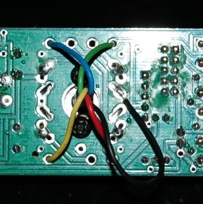
Cannot see the colour codes fully but it all looks right. Only need to add the wire straps between C-E on any BD681 positions where no transistor is fitted.

BD681 is a NPN and a BD680 is a PNP. So will not work in place of the BD681.
 
Thank you Joe, fair play you guys know how to run a company and keep your customers happy :grin:

I'm a little confused with ratio jumper settings.

I figured I don't need any jumpers on the JLM14, 99v, 111DC combo but fitted the jumper block anyway just in case.

I can't find any info on what ratio jumper settings to use for the CMMI-8PCA, none, high or low, any ideas?
 
Knarley Bass - That is a hot looking box! Way sexier than my unlabeled, recycled case.

I just used a pair of BabyA's with JLM14-HybridOpamp-Edcor150:600 after my passive summing mixer. Sounds so sweet! :thumb:

I have a pair with GainBlokes with EdAnderson input (1:7 turns) and output (1:3.5 turns) transformers. Those sound really cool, detailed mids and full lows. I don't know how to describe the highs yet, smooth perhaps.

Now I need to order more BA boards for a Fabio 2520 and FETBlokes.
 
Joe is my hero as well. He's a DIY SuperStar. :cool:

[quote author="TornadoTed"]I figured I don't need any jumpers on the JLM14, 99v, 111DC combo but fitted the jumper block anyway just in case.[/quote]

Yes, no jumpers for the JLM14, as it has only one primary and one secondary winding.

[quote author="TornadoTed"]I can't find any info on what ratio jumper settings to use for the CMMI-8PCA, none, high or low, any ideas?[/quote]

That Cinemag also has only one pri and one sec winding. No jumpers needed, but you should jumper pins 6 and 7 (core and shield) to a nearby ground. There are several unused through holes nearby that join direct to the ground plane.

PDF datasheet from Cinemag.biz
 
Thanks skipwave, much appreciated.

Do I ground pins 6 & 7 just with the CMMI-8PCA, API2520, JLM111DC or with the JLM14, JLM99v, JLM111DC also?
 
The JLM14 doesn't have Pins 6&7. I wonder if that Black wire is the core. Either way, no shield or core connection are made to ground.

Take a look at the overlay of the PCB on the BabyAnimal page: http://www.jlmaudio.com/Baby_Animal_Mic_Pre.htm

Where the input transformer sits, just below the white circle drawn around the words "primary" and "secondary" (the circle represents the physical space that your Cinemag occupies), there is a spare unlabeled through hole that is intended for the shield pin of an OEP transformer and is connected directly to ground. The Cinemag just has the shield brought out to pin 7 instead.
 
This is how I wired the input transformer.

HolidaysCats019.jpg


My tech suggested I solder the black wire to ground, is this an ok place to put it?

Please be patient with me, I've only ever done cables, TT patchbays and changed a few caps in my console before this!
 
Check out this post;
http://www.groupdiy.com/index.php?topic=15245&postdays=0&postorder=asc&start=98

Joe states that the Black wire is not connected.

The transformer is protected enough by being in it's cute little can.

Truth be told, it may not be wise to ground both the core and case to the circuit ground. The Cinemag PDF shows one configuration with the case taken out to chassis ground, not circuit ground, while the core is still attached to circuit ground.

There is some explanation of the shield concept here at the top under "General...":

http://blackmagic.com/ses/bruceg/EMC/isolatrans.html
 
Thanks for the link. I read that thread front to back and made notes of important pages but I guess I missed that section.

I haven't powered these up yet. I should be getting cases from Purusha towards the end of this month/beginning of next month. Hopefully that should coincide with the Cinemag transformers coming from the group buy.

I'll try it out with that black wire connected and then without and report any differneces.

I decided I'd build them ready to be 'boxed' and fired up as I have had a little bit of time this week.
 
[quote author="Knarleybass"]
DSC01580.JPG

DSC01581.JPG

DSC01583.JPG

For the longest time I only had three up and running, I finally got the fourth in the case and working, they sound great![/quote]

Really nice job.

One question, how come the quasi balancing cap and I guess resistors too has been used even when using the output transformers?

My tech told me to leave them out as they weren't used.
 
Skipwave has covered all the questions with great precision :cool: so I will only add the small bits of info below

I figured I don't need any jumpers on the JLM14, 99v, 111DC combo but fitted the jumper block anyway just in case.
The JLM14 only has a primary centre tap black wire which just needs to be left disconnected or like you have done park it on one of the 2 unused pads for the ratio which is fine as long as no ratio jumpers are fitted. If you want a 150ohm input use red and black and discount the green wire. This will give you 1:8 ratio but is only good for 50ohm output microphones.

I can't find any info on what ratio jumper settings to use for the CMMI-8PCA, none, high or low, any ideas?
The CMMI-8PCA only has one primary so wires just like the JLM14 and has no ratio jumpering needed. Also on the CMMI Baby Animal you still need to add a RL=100k.

Do I ground pins 6 & 7 just with the CMMI-8PCA, API2520, JLM111DC or with the JLM14, JLM99v, JLM111DC also?
Yes only on the CMMI BA.

Knarley Bass - That is a hot looking box!
Yes great neat mounting of the output transformers. Only problem is you somehow seemed to have received the wrong knobs with your kit :wink: :grin:

One question, how come the quasi balancing cap and I guess resistors too has been used even when using the output transformers?
Most people just build the PCB up fully just because all the parts are in the kit and it requires less thought and is usually quicker.

If anybody is going to be at the AES in New York please drop by and say hello.
You will get to see several new products from us and we will have a heap of the PCB kits there assembled to look over as well.
If anyone wants a Free VIP "Exhibits Only" pass we have 100 to give away. Contact me by email and I will send you a link to the online registration form.
 
I have 8 channels of these lying around half finished that i almost forgot i had...I should have finished them months ago, but i havent yet... :oops: This thread, and all the nice pictures of completed builds has reminded me that i should complete them soon! You can never have too much gear!
So thanks for reminding me!

I have another question. Would there be any point in experimenting with bypassing the output dc blocking caps with some high quality polypropylene or polystyrene caps to help with high frequency reproduction? I have seen it done in some circuits before, but i have no clue if it would be worth to try here? Perhaps its one of these cases where its different, but not necessarily better or worse?

What value would be good to try (if any)? 10n, 100n, 1u?

I hope this isnt a stupid question. Im just very curious, and like to experiment alot. Im wondering if it would be a waste of time or not.

/J
 
[quote author="JLM Audio"]Skipwave has covered all the questions with great precision :cool: [/quote]

Just trying to be helpful. I know you are busy designing bigger, badder animals. :wink:

[quote author="JLM Audio"]The JLM14 only has a primary centre tap black wire [/quote]

Of course, I should have known that was the center tap. I've edited my post on the last page speculating about that being something else, so as not to cause confusion.
 
I just wanted to show the re-work i've done with my BA's. I wasn't satisfied with the wiring on the units so i rewire 99%. I took the transformers out from the chasis and put them directly to the rack......used shielded wire and i like it better...still not that good but better than before.
Before:
normal_P3240575.JPG


Now:
normal_P9241033.JPG
 
Nice clean up! Lookin' tight. :thumb:

The shielded wire shouldn't make that big of a difference, considering there is no power transformer in the chassis. That eases the requirement for tidy wiredress, a big plus for newbie builders.

Check the crosstalk between the two channels with output transformers. If there is any detectable you could orient them with the windings at a right angle (90 degrees) to each other. That would reduce/eliminate any EM coupling between them.

Brian
 
Hello, I'm just getting my first pair of Baby Animals going, one of them will have an old Sowter 3195 1:7 at the input, what would be a good start for Rl, Rz, Cl, Cz ?
On the Sowter website I could only find this: http://www.sowter.co.uk/specs/3195.htm

What's the best way to check this in general for unknown transformers, put a sqare wave on the input and look for anomalies on the scope?

Oh yes, and should I leave the center tap on the primary side floating?

Thanks!!
 
Hello, I'm just getting my first pair of Baby Animals going, one of them will have an old Sowter 3195 1:7 at the input, what would be a good start for Rl, Rz, Cl, Cz ?
On the Sowter website I could only find this: http://www.sowter.co.uk/specs/3195.htm
From the Sowter page frequency graph. It says it was done with a 25k load (RL). So the 27k load resistor in the normal BA kit should be the best starting value with no CZ, RZ, CZ.

What's the best way to check this in general for unknown transformers, put a square wave on the input and look for anomalies on the scope?
If you use a 500Hz square wave with 200ohm output impedance at low input level you can spot ringing on the secondary easy and experiment with RZ & CZ if the ringing is large. But from the frequency graph and ratio it should be fairly mellow in the high frequencies.

Oh yes, and should I leave the center tap on the primary side floating?
Yes

JLM will be closed from the 1st to the 23rd of October while we attend the AES in New York and then have a short break there and in LA. If you are at the AES please drop by and say hello.

Sneak peak of some new stuff
 
Joe, thanks for your reply, My test oscillator has 600Ω impedance, I'll see what I can do.

Also, great stuff you have coming there, it's always nice to have some Pultec candy in the Lunchbox :thumb:

Marten
 
[quote author="JLM Audio"]Sneak peak of some new stuff[/quote]

Sexy lunchbox thing. Speaker looks like sad robot, with those sullen blue leds as wide set eyes. Cheer up little robot, I'm sure mixes sound amazing through you. :wink: :thumb:
 

Latest posts

Back
Top